background image

12.2019

42/66

H48.HSKFS0023EN

PORTAL

PremiDoor 88
ECO PASS threshold

HS

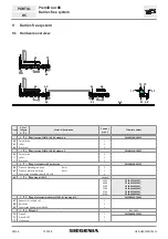
11.2  Hardware list ECO PASS threshold

Item

Pieces for

 scheme

Material descrip on

Content per 

VE

Material number

A

C

Depending on frame width (RAB)

79 1

1

Threshold 

B207

Length

3000
3500
4000
4500
5000
5700
6700

PPBB0780-52401_
PPBB0790-52401_
PPBB0800-52401_
PPBB0810-52401_
PPBB0820-52401_
PPBB0830-52401_
PPBB0840-52401_

80 1

1

Op onal - ECO PASS 

fl

at threshold B203

Length

3000
3500
4000
4500
5000
5700
6700

PPBB1340-52401_
PPBB1350-52401_
PPBB1360-52401_
PPBB1370-52401_ 
PPBB1380-52401_
PPBB1390-52401_
PPBB1400-52401_

81 1

1

ECO 

PASS 

fl

at tread threshold

Length

The 

fl

at threshold is a component of the ECO PASS threshold!

The liability is not fully guaranteed if a threshold is not used!

2000
2500
3500
4500
5000
6700
7000

PPTB0240-52401_
PPTB0250-52401_
PPTB0260-52401_
PPTB0270-52401_
PPTB0280-52401_
PPTB0290-52401_
PPTB0300-52401_

82 

1

1

Running rail 6.5/13

Length

3500
4000
4500
5000
5700
6700

PPLB6260-52401_
PPLB6270-52401_
PPLB6280-52401_
PPLB6290-52401_
PPLB6300-52401_
PPLB6310-52401_

83 1

2

Support 

rail 

Length

1500
2000
2500
3500

PPZB5600-02101_
PPZB5610-02101_
PPZB5620-02101_
PPZB5630-02101_

84 

1

2

Adapter rail PremiDoor 88

Length

1500
2000
2500
3500

PPZB5530-02101_
PPZB5540-02101_
PPZB5550-02101_
PPZB5560-02101_

85 

2

2

Sealing wedge top

Black top

PZUB6010-00003_

Orange - for use in weather bar

PZUB6110-00003_

86 

2

2

Sealing wedge bo om

Violet

PZUB6080-00003_


1

1

Frame corner bracket Premidoor 88 consis ng of:

PMRB0230-02101_

87  

Sealing part B207

2

88  

Seal REV

2

89  

End cap, le

1

90  

End cap, right

1


1

1

Sealing piece MP B08 LH PremiDoor 88

PMRB0242-02101_

91  

Sealing piece MP S102 le

1

92  

End seal B207

1

93  

Sealing pad PremiDoor 88 LH

1

94  

Sealing pad PR 88

1


1

1

Sealing piece MP B08 RH PremiDoor 88

PMRB0241-02101_

95  

Sealing piece MP S102 RH

1

92

End seal B207

1

96  

Sealing pad PremiDoor 88 RH

1

94

Sealing pad PR 88

1

Summary of Contents for PORTAL HS

Page 1: ...ASSEMBLY INSTRUCTIONS PVC Window systems Door systems Comfort systems PORTAL PremiDoor with ECO PASS threshold HS...

Page 2: ......

Page 3: ...9 1 Posi oning locking part G 22 6 9 2 Posi oning the raised countersunk head screw 23 7 BURGLAR RESISTANCE 24 7 1 Hardware components RC2 24 7 2 Hardware components RC3 25 7 3 Hardware list RC2 and...

Page 4: ...ries for threshold 51 13 1 1 Fixing sequence 51 14 BASE PROFILE 53 15 SOFT CLOSE 54 15 1 SOFT CLOSE hardware overview 54 15 2 Milling on sliding sash 55 15 3 Posi oning the trigger 55 15 4 Inser ng th...

Page 5: ...pa o doors Guidelines and notes for end users The VHBH also contains informa on concerning instruc on obliga on The instruc on obliga on informa on concerning which documents and informa on must be h...

Page 6: ...ould occur When addi onal loads have an impact on window or pa o door sashes for example when children rock on the window or pa o door sashes If hands are placed in the rebate between the frame and sa...

Page 7: ...sidera on of the intended installa on site applica on Tes ng the resistance against wind load in accordance with EN 12211 and classifica on in accordance with EN 12210 Tes ng the impact resistance in...

Page 8: ...t la poign e dans la position fermeture et l arr ter env 10 mm avant la fin de course Ne pas possible pour Sch ma G 10003 Spaltl ftungsposition night vent positon position ventilation fente Verschlu s...

Page 9: ...person on request 4 2 Applica on diagram Itisessen altoobservetheapplica ondiagramforPORTALHS H58 AWD_P_S004EN You can obtain applica on diagrams from the sales contact person on request 4 3 Test rep...

Page 10: ...1288 2600 1288 2600 Sliding sash width FBS 737 3000 737 2600 Sash height FH sliding sash 1156 24681 1156 24681 The FH is reduced by 8 mm for barrier free elements Gear backset 37 5 Sash weight max 40...

Page 11: ...L HS 5 Basic hardware 5 1 Hardware components scheme A 5 5 121 101 26 14 21 121 12 20 19 13 2 8 8 24 15 7 6 16 16 1 4 22 23 18 See choice of handles 1 Only with use of the guiding rail from PremiDoor...

Page 12: ...8 Countersunk tapping screw 4 8 x 50 for bogie wheels 1 Countersunk tapping screw 4 8 x 32 for corner drive and bogie wheels 5 1 Carton PORTAL HS PVC PremiDoor 88 scheme C PMZB4180 10001_ 5 Distance p...

Page 13: ...PMZB1300 00001_ Damper 1 Locking washer 1 Spiral pin 1 Informa on of sash height FH for installed guiding rail from SIEGENIA If the PremiDoor guiding rail is used the sash height FH is 31 mm less Dep...

Page 14: ...screwing the corner drive 6 3 Installa on of corner drive LV FB Sash width LV Length of connec ng rod up to 300 kg from 301 kg LV FB 658 LV FB 1274 1 max 8 Nm 4 2x 2 Insert the connec ng rod into the...

Page 15: ...rofile with the corresponding screws Clip the cover profile into the corner drive 6 4 Installa on of bogie wheels 1 2 2x 2x 4 S1 Countersunk tapping screw B 4 8 x 32 S1 S1 max 8 Nm A ach bogie wheels...

Page 16: ...1 Gear drills on sliding sash 90 210 16 80 69 16 38 5 12 20 20 Grip posi on for running rail 6 5 5 barrier free Gear size G 170 398 220 260 998 Grip posi on for running rail 6 5 13 Gear size G 170 40...

Page 17: ...88 Assembly of basic hardware PORTAL HS 6 5 2 Milling the sliding grip 92 12 26 38 5 Grip posi on for running rail 6 5 5 barrier free Gear size G 170 398 220 260 998 Grip posi on for running rail 6 5...

Page 18: ...HS 6 5 3 Fixing gear Abb 2 Fixing gear Connect to bogie wheels 1 2 Cut to length Screw on GL Gear length FH Sash height S3 Countersunk tapping screw B 4 8 x 70 Gear length for guiding rail SIEGENIA w...

Page 19: ...arts Posi on on frame Gear size A B1 C1 170 1000 600 220 1600 1200 750 260 1900 1200 750 Posi on on secondary sash Gear size A B1 C1 170 996 596 220 1596 1196 746 260 1896 1196 756 1 For burglar resis...

Page 20: ...segment should amount to the sliding sash width FBS 100 Fix the short segment of the guiding rail in the frame Moun ng posi on on the locking side of the sliding sash 1 2 1 Place sliding sash on the r...

Page 21: ...hed in the shearing zone Mount a stop stopper for the sliding sash A shearing zone will hence be prevented Min 20 A B A Sliding sash B Fixed sash Select the posi on for the stop to ensure that a gap o...

Page 22: ...ning rail Drill the screw hole for the countersunk screw M6x20 Main and secondary sashes must be labelled accordingly to prevent faulty opera on The sliding sashes may be operated only in the order sp...

Page 23: ...he raised countersunk head screw 25 50 1 2 A Raised sliding sash A 1 80 Posi on from the locking side of the closed primary sash Pre drilling the screw hole is recommended When the sliding sash is li...

Page 24: ...19 24 66 H48 HSKFS0023EN PORTAL PremiDoor 88 Burglar resistance HS 7 Burglar resistance 7 1 Hardware components RC2 Presenta on with bogie wheels for running rail 6 5 13 31 32 36 34 38 33 33 35 30 29...

Page 25: ...H48 HSKFS0023EN 12 2019 25 66 PremiDoor 88 Burglar resistance PORTAL HS 7 2 Hardware components RC3 Presenta on with bogie wheels for running rail 6 5 13 31 32 41 34 38 33 33 39 40 30 29 42 42...

Page 26: ...PremiDoor 88 scheme A PMZB4690 00001_ 34 RC plate PremiDoor 88 300 mm 1 35 Locking part G 1 36 Countersunk head screw PH M6x20 1 37 Pan head self tapping screw PH B6 3 x 38 2 38 Screw for frame part 5...

Page 27: ...glaze P Only for scheme C Fix the profine aluminium faceplate strip using clip screws every 200mm 35 mm long screws are used for the side screwing so that 2 PVC bars provide a stronger grip 7 4 1 Adhe...

Page 28: ...3 4 Glue the central locks into place with addi onal PVC adhesive profine C004 Apply the PVC glue to the en re length of the strip 5 6 to 400 mm top end 80 80 80 80 to 500 mm 80 80 80 80 bo om end Fi...

Page 29: ...fine cover profile to the fixed sash 1 23 14 5 2 1 2 Trim the profile cover strip to the required length Notch the top corner Apply the C004N glue at intervals of 400 mm along the en re length of the...

Page 30: ...in the complete catch area of the RC plate 1 2 100 Insert RC2 plate into the profile of the sealing rail on the sliding sash Posi on the RC2 plate Centre from bo om edge of sash 3 8x 3 0 Screw the RC...

Page 31: ...RC3 plate into the profile of the sealing rail on the sliding sash to be flush with the bo om edge Screw the RC2 plate through profile of the sealing rail to the sliding sash Use frame part screw 5x5...

Page 32: ...iding sash completely open Pre drill the screw hole When the sliding sash is li ed the interval between the screw head and the top edge of the sliding sash should not exceed 1 mm 7 8 Fixing locking pa...

Page 33: ...PremiDoor 88 Hook bolt gear PORTAL HS 8 Hook bolt gear 8 1 Hardware components hook bolt gear 43 50 52 52 53 53 541 551 561 56 571 57 55 541 51 51 44 44 48 48 46 46 47 58 59 47 1 Only with use of the...

Page 34: ...ries HS PVC hook bolt gear A PremiDoor 88 PMZB4550 100010 45 2 Frame part SHG 46 2 Packer SHG 22 5 mm 47 2 Screen SHG PremiDoor 88 48 4 Countersunk screw DIN 965 M5x40 49 2 Screen SHG PremiDoor 88 50...

Page 35: ...SKFS0023EN 12 2019 35 66 PremiDoor 88 Hook bolt gear PORTAL HS 8 3 Frame milling Abb 4 Frame milling hook bolt gear Upper edge of running rail A B 101 101 22 Size A B Size 220 300 1540 Size 260 300 18...

Page 36: ...locking piece 1 2 Place locking piece on frame part Insert locking piece into the frame milling 3 3 4x 4 Pre drill locking piece screwing Screw locking piece and frame part firmly in place Use 4x40 s...

Page 37: ...37 66 PremiDoor 88 Hook bolt gear PORTAL HS 8 4 1 Adjustment of hook bolt locking piece Locking Night vent 6 8 4 2 Adjustment of locking piece Adjus ng the compression Increase the compression Reduce...

Page 38: ...orner drive 1 61 roller 1 62 Brush seal 1 1 Bag of sash parts HS barrier free PMZB0540 09701_ 64 Distance plate bogie wheels 8 mm 1 65 Distance plate corner drive 8 mm 1 Countersunk tapping screw B 4...

Page 39: ...opper for the sliding sash A shearing zone will hence be prevented Min 20 A B A Sliding sash B Fixed sash Select the posi on for the stop to ensure that a gap of of 20 mm is maintained in the shearing...

Page 40: ...76 2 4 Cover profile for bogie wheels HS 300 2 5 mm VE 1 piece PZUB1090 09901_ from 200 kg sash weight 1 piece per corner drive bogie wheels VE 20 piece PZUB1090 09903_ 10 1 2For threshold with runni...

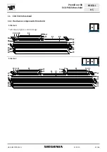
Page 41: ...ld PORTAL HS 11 ECO PASS threshold 11 1 Hardware components threshold Scheme A Le shown right is a mirror image 79 80 90 88 82 91 93 83 93 84 92 85 85 86 86 87 87 88 89 81 Scheme C 79 80 90 88 82 91 9...

Page 42: ...1_ PPTB0280 52401_ PPTB0290 52401_ PPTB0300 52401_ 82 1 1 Running rail 6 5 13 Length 3500 4000 4500 5000 5700 6700 PPLB6260 52401_ PPLB6270 52401_ PPLB6280 52401_ PPLB6290 52401_ PPLB6300 52401_ PPLB6...

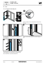
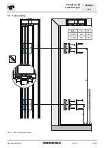
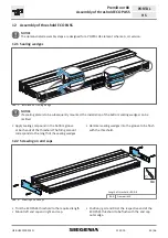
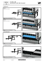
Page 43: ...f the bo om sealing wedges can be omi ed Apply sealing compound in the bo om groove at both ends of the threshold The filing amount corresponds to the length of the sealing wedges Hammer sealing wedge...

Page 44: ...10 max 2 2 1 1 2 2 2 6 5 6 5 1 2 10 max 2 2 2 1 2 1 2 12 4 Frame corner connector Abb 7 Screw frame corner connector into place 6x 4 2x30 Apply sealing compound to the fixing area of the threshold Pos...

Page 45: ...y elas c sealing compound along the en re length of the groove on the threshold Adjust running rail according to the posi oning groove and clip onto the threshold 12 6 Seal REV Abb 9 Moun ng the seal...

Page 46: ...hen remove any saw burr 1 Apply permanently elas c sealing compound to sealing piece REV 2 Trim the end seal B176 and then glue to support rail 3 Place support rail on threshold In the corner press ag...

Page 47: ...ng compound Posi on sealing piece MP on threshold and press with cam into the support rail and secure with 4 2 x 30 mm screws 12 10 Sealing pad Abb 13 Moun ng the sealing pad Clean up adhesive points...

Page 48: ...Abb 14 Moun ng the sealing pad 1 Clean up adhesive points 2 Remove the foil from the adhesion surface 3 Posi on the flat threshold and glue to the threshold 12 12 Sealing the threshold Abb 15 Moun ng...

Page 49: ...2401_ PPTB0360 52401_ PPTB0360 52401_ 98 1 2 Compensa on rail Length 3500 4500 6700 PPZB0700 52401_ PPZB0710 52401_ PPZB0720 52401_ 99 1 1 Bag drill screw T STAR 15 x 3 9 4 piece per metre threshold 1...

Page 50: ...2401_ PPAB0080 52401_ 102 1 1 Sealing rail horizontal small Length 3500 4000 4500 5000 5700 6700 PPAB0640 52401_ PPAB0630 52401_ PPAB0620 52401_ PPAB0610 52401_ PPAB0600 52401_ PPAB0590 52401_ 103 1 1...

Page 51: ...ate high 1 2 3 Prior to fixing the sealing plate apply sealing compound along the en re length of the moun ng groove Clip sealing plate into the moun ng groove of the threshold For assembly of a seali...

Page 52: ...reshold HS 4 Weather bar S1 S1 Bag drill screw T STAR 15x3 9 Version 1 Fixing on the threshold S1 S1 Bag drill screw T STAR 15x3 9 Version 2 Fixing on the threshold 5 Tread threshold S1 S1 Bag drill s...

Page 53: ...orma on for base profile SH SH base height Lining During assembly of the base profile the threshold must be laid levelly or lined Especially in the area of a poten ally existent joint The length of th...

Page 54: ...aterial number A C 1 2 SOFT CLOSE HH PVC Sash weight 105 1 2 SOFT CLOSE HH PVC 100 kg 101 kg 200 kg 201 kg 400 kg PSCB0120 02101_ PSCB0130 02101_ PSCB0140 02101_ 106 1 2 SOFT CLOSE trigger 2 2 Accesso...

Page 55: ...gh the recess in the guiding rail Is there is no recess one must be created at the end of the guiding rail 465 4 max 4 Nm Fi ng dimension Accurate posi oning of the trigger is required following insta...

Page 56: ...SE into the sash milling Pre drill posi on fixing holes at both ends Drill posi on fixing holes with larger drill bit 3 2x 4 Push distance plates onto fixing bolt Posi on SOFT CLOSE in the profile Scr...

Page 57: ...ry from the catch snapping back The quick jack knifing of the catch hook just before it engages could cause fingers to be crushed To tension the SOFT CLOSE press the catch hook against a stable edge e...

Page 58: ...50201_ PKHB0060 52401_ Carton handle Si line PORTAL HS 300 RZ inside for lockable elements with profile half cylinder inside and outside only in conjunc on with handle Si line HS 300 PZ outside H1 1 H...

Page 59: ...inside with 100 mm spindle length RAL 9003 RAL 8022 EV 1 silver PHIB0090 00201_ PHIB0090 01201_ PHIB0090 02501_ Bag of accessories HS 200 300 handle for lockable elements with profile half cylinder i...

Page 60: ...installa on with threshold 17 2 Reveal connec on No special requirements need be taken into account for the sealing in the reveal area for connec on heights with 60 mm over the wear level In the bo o...

Page 61: ...cross sec ons 18 1 SI construc on drawings The dimensions of the SI construc on drawings must be observed for the correct posi oning of the holes and the components on the profile You can obtain SL co...

Page 62: ...ls Jig has 38 5 backset Drill 12 mm 20 mm Milling template for sliding grip PABB4110 00001_ Jig has 38 5 backset Milling cu er 20 Guide ring 27 Centre punch PVC PALB4010 10001_ for locking parts Jig H...

Page 63: ...cleaning agent to 5 litres of water is the guideline for the dose Most dirt can be removed with this detergent solu on Leave the cleaning agent to react for maximum 10 minutes A er cleaning always rin...

Page 64: ...s on cleaning in the informa on sheet Cleaning and maintenance of PVC windows of the German Quality Associa on for PVC Window Profile Systems G tegemeinscha Kunststo Fensterprofilsysteme e V h ps www...

Page 65: ......

Page 66: ...www siegenia com H48 HSKFS0023EN 7...

Reviews: