background image

01.2022

32/108

H48.HSKFS0031EN

PORTAL

PremiDoor 76, 

PremiDoor 76 Lux

Assembly of basic hardware

HS

6.14 

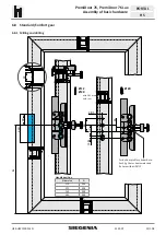
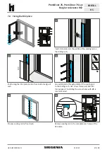
 Stop buffer

6.14.1 

 Stop buffer rod

15

Assembly.

without 

spacers

Assembly.

with 

spacers

Reinforcement 

V372

Reinforcement 

V371

1

When reinforcement V192 is installed in the 

sliding.sash,.two.spacers.D20.must.be.mounted

2

2x

4.8x38

Fix.stop.buffer.rod.to.the.profile.with.drill.screws.

Fixing.position.for.stop.buffer.rod.on.the.sliding.sash.

3

4

Dimension.with.lifted.sash

Summary of Contents for PremiDoor 76

Page 1: ...ASSEMBLY INSTRUCTIONS PVC Window systems Door systems Comfort systems PORTAL HS PremiDoor 76 PremiDoor 76 lux...

Page 2: ......

Page 3: ...of corner drive 23 6 6 Installation of the bogie wheels 24 6 7 Block setting running elements 24 6 8 Standard Comfort gear 25 6 8 1 Milling and drilling 25 6 8 2 Milling the sliding grip 26 6 8 3 Fixi...

Page 4: ...ng plate or sealing strip 75 13 1 2 Sealing strip vertical 75 13 1 3 Sealing bead horizontal small 75 13 1 4 Weather bar 76 13 1 5 Threshold 76 13 1 6 Compensation rail EP 76 14 SUBSTRUCTURE PROFILES...

Page 5: ...100 24 CLEANING AND MAINTENANCE 100 25 OPTIONAL ACCESSORY COMPONENTS 102 25 1 Packer for stop 102 25 2 Distance piece for bogie wheels 102 25 3 Additional locking parts 103 25 3 1 Packer for locking p...

Page 6: ...ferent languages here http www beschlagindustrie en ggsb richtlinien asp VHBH Hardware for windows and patio doors Specifications and notes on the product and on liability VHBH Hardware for windows an...

Page 7: ...us parts of windows or patio doors are damaged or destroyed or if subsequent damage could be caused when window sashes or patio door sashes are subjected to additional loads for example children rocki...

Page 8: ...ith EN 12211 and classification in accordance with EN 12210 Testing the impact resistance in accordance with EN 13049 If any special manufacturing instructions or fabrication guidelines exist they mus...

Page 9: ...tournant la poign e dans la position fermeture et l arr ter env 10 mm avant la fin de course Ne pas possible pour Sch ma G 10003 Spaltl ftungsposition night vent positon position ventilation fente Ve...

Page 10: ...quently If a deviation of the system dimensions is ony determined after the installation of the windows the hardware manufacturer will assume no liability for any potential additional expenditure 4 1...

Page 11: ...at intervals of 300 mm for pressure resistance and sound absorption You must use stainless steel screws for the installation of components on the threshold ECO PASS You can find information on the to...

Page 12: ...0 737 2600 737 2600 from 301 kg 1594 3000 1594 2600 1594 2600 Sash height FH sliding sash 1202 2460 1202 2260 1202 2260 Gear backset 37 5 Sash weight max 400 kg Ratio sash height FH sash width FB 2 5...

Page 13: ...Basic hardware PORTAL HS 5 Basic hardware 5 1 Hardware components scheme A Scheme A Scheme C 2 1 Scheme G3 Scheme K 9 15 14 25 13 28 22 16 16 25 26 26 32 33 24 27 27 2 3 3 12 8 8 7 12 30 21 6 5 11 20...

Page 14: ...oor 76 PremiDoor 76 Lux Basic hardware HS 5 2 Hardware components scheme C secondary sash 14 25 26 26 32 33 24 27 27 18 17 9 25 28 19 22 16 16 3 3 12 12 30 21 43 31 4 6 2 5 29 23 23 See choice of hand...

Page 15: ...15 108 PremiDoor 76 PremiDoor 76 Lux Basic hardware PORTAL HS 5 3 Hardware components scheme D Inner running sash Scheme D 9 15 14 13 22 2 3 3 12 8 8 7 12 21 6 5 11 20 44 10 43 31 1 19 23 23 See choi...

Page 16: ...KFS0031EN PORTAL PremiDoor 76 PremiDoor 76 Lux Basic hardware HS Outer running sash Scheme D 9 15 14 42 13 22 40 2 3 3 12 8 8 7 12 21 39 6 5 11 28 29 30 20 44 10 43 31 1 19 23 41 38 37 23 36 See choic...

Page 17: ...arts scheme A 4 Countersunk tapping screw B 4 8x65 for gear 8 Countersunk tapping screw B 4 8x50 for bogie wheels 1 Countersunk tapping screw B 4 8x32 not required 5 1 Carton PORTAL HS PVC PremiDoor 7...

Page 18: ...7040 PMZB0140 0E601_ RAL 9005 831922 28 Stop 1 29 Countersunk tapping screw B 4 8x70 1 30 Cover cap 1 31 1 2 2 1 2 HS comfort gear damper kit PMZB1300 00001_ damper 1 locking washer 1 Spiral pin 1 32...

Page 19: ...GKB4070 52401_ PGKB4080 52401_ from 201 kg sash weight Information of sash height FH for installed SIEGENIA guiding rail without top front guide An optimised size range with the gear size 280 IN CONJU...

Page 20: ...y of basic hardware HS 6 Assembly of basic hardware 6 1 Milling the sliding sash 400 80 300 85 22 Sliding sash more than 300 kg 40 40 80 345 345 85 395 300 6 2 Inserting the distance piece Insert dist...

Page 21: ...c hardware PORTAL HS 6 3 Installation of sealing brush 1 2 Fix sealing brush on corner drive and bogie wheels Apply instant glue to the end of the brush groove 3 4 Slide the sealing brush into the bru...

Page 22: ...e HS 6 4 Installation of distance pieces Fix distance pieces properly to corner drive and bogie wheels Observe the correct fixing method Wrong clip on can lead to damage of the distance pieces Click C...

Page 23: ...stance plate to the corner drive Insert the connecting rod into the striker packer of the corner drive and fix with dowel pin 3 3 S1 S2 S2 S1 S1 1x 4 8x50 S1 3x 4 8x38 Insert the corner drive with con...

Page 24: ...heels with striker packer to the connecting rod 2 4 max 8 Nm 2x 4 8x38 4 Fix the bogie wheels with dowel pins Tightening torque max 8 Nm Fix to the profile with screws Clip the cover profile into the...

Page 25: ...ardware PORTAL HS 6 8 Standard Comfort gear 6 8 1 Milling and drilling 90 210 16 80 69 16 38 5 12 20 20 22 Handle position Gear size G 170 398 220 998 260 998 280 998 G For bottom profile cylinder bor...

Page 26: ...1EN PORTAL PremiDoor 76 PremiDoor 76 Lux Assembly of basic hardware HS 6 8 2 Milling the sliding grip 92 12 26 38 5 Position of sliding grip identical to grip seat G G Handle position Gear size G 170...

Page 27: ...ORTAL HS 6 8 3 Fixing the gear GL Length of gear FH sash height S3 Countersunk tapping screw B 4 8x65 Cropping 1 Connect to bogie wheels 2 Connect to bogie wheels 3 S3 Gear length Guiding rail from SI...

Page 28: ...1600 1200 750 250 260 1900 1200 750 250 280 2200 1200 750 250 Position on secondary sash Gear size A B1 C1 D 170 996 596 246 220 1596 1196 746 246 260 1896 1196 756 246 280 2196 1196 756 246 1 For bur...

Page 29: ...18 Fix a slat piece 18 mm wide in the gear slot as a stabiliser 3 1 2 The assembly position for the damper kit Insert the damper into the intended point and fix with the dowel pin Then flap up the dam...

Page 30: ...ut the guiding rail into two segments prior to inserting the sliding sash See the fabrication guidelines for separation of the guiding rail Fix a part of the guiding rail in the frame Select mounting...

Page 31: ...rts in the shearing zone can be severed or crushed Mount a stop stopper for the sliding sash This will prevent a shearing zone min 25 A B A Sliding sash B Fixed sash Choose the position for the stop e...

Page 32: ...rod 15 Assembly without spacers Assembly with spacers Reinforcement V372 Reinforcement V371 1 When reinforcement V192 is installed in the sliding sash two spacers D20 must be mounted 2 2x 4 8x38 Fix s...

Page 33: ...AL HS 6 14 2 Spacer D20 1 4 2 20 Predrill the fixing holes for spacers Drill the fixing holes for spacers 3 4 2x 4 8x60 Insert D20 spacers into the profile Fix stop buffer rod to the profile with scre...

Page 34: ...parts in the shearing zone can be severed or crushed Mount a stop stopper for the sliding sash This will prevent a shearing zone min 25 A B A Sliding sash B Fixed sash Select the position for the stop...

Page 35: ...he gear to the running rail and centre punch the hole for countersunk screw M6 x 20 Drill hole with drill bit 5 2 mm Fix locking part G to the running rail using the countersunk screw M6 x 20 The prim...

Page 36: ...idge Gasket bridge 30 12 1 Installation of the gasket bridge 30 12 on the outer running sliding sash Apply sealant to the installation position 2 35 3 Position the guides in the top profile groove of...

Page 37: ...le The installation position of the gasket bridge 88 12 is 13 5 mm from the bottom edge of the sash 3 9x25 2x Position gasket bridge 88 12 between the guiding rails Fix gasket bridge 88 12 in the fram...

Page 38: ...osition is flush with the guiding rail Fix with drill screw 6 17 3 Impact seal 1 2 Remove the protective paper from the adhesive film Glue the impact seal to the front surface of the outside longer gu...

Page 39: ...part seal in the outer running sliding sash Apply sealant to the installation position Apply sealant to the installation position 2 3 Push the sash part seal into the profile 6 17 5 Sealing pad 1 Inst...

Page 40: ...hen the sliding sash is opened Bodily parts in the shearing zone can be severed or crushed Mount a stop stopper for the sliding sash This will prevent a shearing zone min 25 A B A Inside sliding sash...

Page 41: ...H48 HSKFS0031EN 01 2022 41 108 PremiDoor 76 PremiDoor 76 Lux Assembly of basic hardware PORTAL HS 3 Position the stop in the hole with the bolt The stopper indicates the direction of the sliding sash...

Page 42: ...01 2022 42 108 H48 HSKFS0031EN PORTAL PremiDoor 76 PremiDoor 76 Lux Burglar resistance RC2 HS 7 Burglar resistance RC2 7 1 Hardware components RC 2 54 52 56 51 51 53 48 47 49 50 55 55 57 57...

Page 43: ...3 PMHB0020 50201_ RAL 8022 PMHB0020 51201_ 1 2 1 2 Basic carton PORTAL HS scheme C PMKB1310 10001_ 49 Corner drive 1 50 Roller 1 51 Sealing brush 1 1 1 Set RC2 PremiDoor 76 Scheme A Colour EV 1 silver...

Page 44: ...number V373 Glue around the glazing rebate with K diglaze P Only for scheme C Fix aluminium faceplate strip profine number A390 using 200 mm clip screws 35 mm long screws are used for the side screwin...

Page 45: ...ue the centre locks 76657 into place with additional PVC adhesive profine C004 Apply the PVC glue to the entire length of the strip 5 6 to 400 mm at the top end 80 80 80 80 to 500 mm 80 80 80 80 at th...

Page 46: ...ile 76656 on the fixed sash 1 19 17 5 2 1 2 Trim the cover strip 76656 to the required length Notch the top corner 1 Insert seal G075 and glue the ends to the profile 2 100 mm from the profile end app...

Page 47: ...g rail on the sliding sash 2 100 3 8x 3 0 Positioning the RC2 plate Centre from bottom edge of sash Screw RC2 plate through profile of the sealing rail to the sliding sash Use screw frame part 5x55 fo...

Page 48: ...liding sash completely open Predrilling the screw hole is recommended With the sliding sash lifted the interval between the screw head and the top edge of the sliding sash should not be more than 1 mm...

Page 49: ...9120 52401_ 260 2048 2468 PGKB9130 52401_ OZ comfort gear 220 1748 2047 PGKB9160 52401_ 260 2048 2468 PGKB9170 52401_ RZ RZ standard gear 220 1748 2047 PGKB9220 52401_ 260 2048 2468 PGKB9230 52401_ RZ...

Page 50: ...f hook bolt gear 8 1 1 Milling and drilling the sliding sash 90 210 150 16 80 69 16 38 5 12 20 20 150 22 Handle position Gear size G H1 H2 170 398 220 998 309 1549 260 998 309 1849 G H1 H2 For bottom...

Page 51: ...H48 HSKFS0031EN 01 2022 51 108 PremiDoor 76 PremiDoor 76 Lux Hook bolt gear PORTAL HS 8 1 2 Milling the frame A B 101 101 22 Upper edge of running rail Gear size A B 220 300 1540 260 300 1840 10...

Page 52: ...gear locking piece 1 2 Attach locking piece to frame part Insert locking piece into the frame milling 3 3 4x40 4x 4 Pre drill locking piece screwing Screw locking piece and frame part firmly in place...

Page 53: ...76 PremiDoor 76 Lux Hook bolt gear PORTAL HS 8 2 1 Adjustment of hook bolt locking piece Lock gap ventilation night vent 6 8 2 2 Adjustment of locking piece Adjustment of compression Increasing the co...

Page 54: ...66 65 65 65 68 67 67 68 Item VE for scheme Material description Content per VE Material number A C G3 K 1 2 1 2 Carton of accessories HS400 8 5 PMKB1340 10001_ 63 2x bogie wheels M 8 5 2 64 2 x short...

Page 55: ...nnecting rod 2 bogie wheels M 3 bogie wheels M with connecting rod 4 bogie wheels with connecting rod 1 4 4 max 8 Nm 2 Insert the connecting rod into bogie wheels M and fix with grub screws M8x1 Inser...

Page 56: ...10 1 Hardware components Premidoor 76 Scheme A RH as shown LH mirror image 80 78 72 71 81 82 77 77 78 79 69 70 74 75 75 76 76 73 Scheme C 80 78 72 81 82 82 77 77 78 79 69 70 74 74 75 75 76 76 73 73 7...

Page 57: ...108 PremiDoor 76 PremiDoor 76 Lux ECO PASS threshold PORTAL HS Scheme K 80 78 72 81 77 77 78 79 69 70 74 75 75 76 76 73 71 71 83 Scheme D LH shown RH is a mirror image 80 78 72 87 72 77 77 78 88 79 69...

Page 58: ..._ PPTB0300 52401_ 72 1 1 2 1 1 Running rail M 5 Length 3500 4000 4500 5000 5700 6700 7000 PPLB6030 52401_ PPLB6160 52401_ PPLB6040 52401_ PPLB6170 52401_ PPLB6180 52401_ PPLB6060 52401_ PPLB6070 52401...

Page 59: ...for scheme Material description Contents per VE Material number D 11 Sealing piece MP B179 LH groove PremiDoor 76 PMRB4242 02101_ 84 Sealing piece MP B179 LH groove 1 85 End seal B179 PremiDoor 76 1 1...

Page 60: ...SS threshold HS 10 4 Hardware components Premidoor 76 Lux The displayed hardware components are used additionally to or deviating from the PremiDoor 76 system Scheme A RH as shown LH mirror image 90 9...

Page 61: ...ing and fixed sash 1 91 End seal PR76 Lux between support rail and REV 1 11 1 1 Sealing part MP leftPremiDoor 76 Lux PMRB6302 02101_ 92 Sealing piece MP PR76 Lux LH between sliding and fixed sash 1 91...

Page 62: ...ling wedges can be omitted 1 Apply sealing compound in the bottom groove at both ends of the threshold The filing amount corresponds to the length of the sealing wedges 2 Hammer sealing wedges into th...

Page 63: ...5 1 2 10 max 2 2 2 1 2 1 2 Position the jig on the threshold to be flush with the end cap Drilling template for the screwing of the LH frame corner connector Drilling template for the screwing of the...

Page 64: ...ply permanently elastic sealing compound to the entire length of the groove in the threshold 2 Adjust running rail according to the positioning groove and clip onto the threshold 11 6 Seal REV 3 2 1 4...

Page 65: ...equired length Remove the saw burr 1 Apply permanently elastic sealing compound to the sealing piece REV 2 Trim the end seal B176 and then glue to support rail 3 Place support rail on threshold In the...

Page 66: ...permanently elastic sealing compound 2 Position sealing piece MP on threshold and press with cam into the support rail and secure with 4 2 x 30 mm screws 11 10 Sealing pad The Profine sealing pad M43...

Page 67: ...remiDoor 76 Lux Assembly of threshold ECO PASS PORTAL HS 11 11 Flat threshold 1 Clean the adhesion points 2 Remove the foil from the adhesion surface 3 Position the flat threshold and glue to the thre...

Page 68: ...x 4x30 1 Apply permanently elastic sealing compound to the end of the support rail and to the area for positioning the sealing piece MP 2 Fix the MP sealing piece to the threshold 11 13 2 Positioning...

Page 69: ...HS 11 13 3 Fixing the supporting rail Length of the supporting rail 1 Crop the supporting rail to the required length 2 Clip the supporting rail onto the distance plate 4x30 60 60 3 Fix the supporting...

Page 70: ...4 Additional running rail LLS LLS Length of running rail The dimensions can be taken from the construction drawing 1 Apply permanently elastic sealing compound along the entire length of the groove Co...

Page 71: ...ly elastic sealing compound 2 Position sealing piece MP on threshold and press with cam into the support rail and secure with 4 2 x 30 mm screws 11 14 2 Compensation rail 1 Apply permanently elastic s...

Page 72: ...1 Clean the adhesion points 2 Remove the foil from the adhesion surface 3 Position the flat threshold and glue to the threshold 11 14 4 Centering disks 4x20 1 Fix the centering disks to the bottom si...

Page 73: ...1 2 Compensation rail Length 3500 4500 6700 PPZB0700 52401_ PPZB0710 52401_ PPZB0720 52401_ 98 depending on length Bag drill screw T STAR 15 x 3 9 4 piece per metre threshold PZUB0600 00001_ 99 1 1 1...

Page 74: ...0 4500 5000 5700 6700 PPAB0370 52401_ PPAB0380 52401_ PPAB0390 52401_ PPAB0400 52401_ PPAB0410 52401_ PPAB0420 52401_ 102 1 1 1 1 1 Sealing bead horizontal small Length 3500 4000 4500 5000 5700 6700 P...

Page 75: ...2 3 Before fixing the sealing plate apply sealing compound to the entire length in the groove Clip the sealing plate into the mounting groove of the threshold For assembly of a sealing strip horizonta...

Page 76: ...from variant B50 to be step resistant S1 S1 BAG drill screw T Star 15x3 9 Variant 1 Fixing on the threshold S1 S1 BAG drill screw T Star 15x3 9 Variant 2 Fixing on the threshold B20 B50 B90 B100 Suppo...

Page 77: ...00001_ PSPB0260 00001_ PSPB0270 00001_ 2 2 1 1 1 1 1 106 Bag set fixing up for fixing of substructure profile to the threshold 5x chipboard screws SK 5x washers DIN9021 M10 40 60 80 100 120 140 160 P...

Page 78: ...1EN PORTAL PremiDoor 76 PremiDoor 76 Lux Substructure profile HS 14 2 Assembly of substructure profile 14 2 1 Apply sealant 14 2 2 Fixing on the threshold 300 300 300 300 100 100 6x TX30 Screw length...

Page 79: ...profile and lining Screw heads must be flush Screw length dependent on base height SH 70 101 89 115 14 2 4 Lining The base profile must be lined at intervals of 300 mm to be pressure tight and sound a...

Page 80: ...01 2022 80 108 H48 HSKFS0031EN PORTAL PremiDoor 76 PremiDoor 76 Lux Substructure profile HS 14 2 5 Fixing the extension profile 300 300 300 300 100 100 6x120 TX30...

Page 81: ...r A C D G3 K 1 1 2 1 2 Basic carton PORTAL HS 8 5 HV scheme A PMKB1320 1000_ 110 Corner drive 1 111 Roller 1 112 Sealing brush 1 1 Basic carton PORTAL HS 8 5 HV scheme C PMKB1330 1000_ 113 Corner driv...

Page 82: ...nts HV 15 2 1 Milling and drilling the sliding sash 400 80 355 30 22 Perform milling for the corner drive and bogie wheels HV on the sliding sash 1 12 35 2 Drill the opening for the height adjustment...

Page 83: ...Wait until the glue has dried Cut off any projecting sealing brush 15 3 Installation of distance pieces Fix distance pieces properly to corner drive and bogie wheels Observe the correct fixing method...

Page 84: ...nce plate to the corner drive Insert the connecting rod into the striker packer of the corner drive and fix with dowel pin 3 4 S1 S2 S2 S1 S1 1x 4 8x50 S1 3x 4 8x38 Insert the corner drive with connec...

Page 85: ...els with striker packer to the connecting rod 3 4 max 8 Nm 2x 4 8x38 4 Fix the bogie wheels with dowel pins Tightening torque max 8 Nm Fix to the profile with screws Clip the cover profile into the bo...

Page 86: ...PremiDoor 76 Lux Height adjustable running elements HS 15 3 4 Adjustment of bogie wheels HV 4 10 4 10 Guide the hexagon wrench through the hole in the sash into the adjustment screw on the bogie wheel...

Page 87: ...0140 02101_ 118 1x trigger SOFT CLOSE 1 2 1 2 Accessories HS PVC SOFT CLOSE distance plate 3 mm PZUB0550 02111_ 119 2x distance plates 3 mm 120 1 1 1 1 Guiding rail PremiDoor 76 Length Required for us...

Page 88: ...h Insert trigger through the recess in the guiding rail If there is no recess one must be produced at the end of the guiding rail 465 4 max 4 Nm Fitting dimension Accurate positioning of the trigger i...

Page 89: ...Insert SOFT CLOSE into the sash milling Pre drill position fixing holes at both ends Drill positions fixing holes with drill 8 3 4 4x25 4x Push distance plates onto fixing bolt Position SOFT CLOSE in...

Page 90: ...T CLOSE before you install it in the sliding element 17 5 SOFT CLOSE troubleshooting Fault SOFT CLOSE is not functioning Possible cause SOFT CLOSE is not tensioned Rectification Subsequent tensioning...

Page 91: ...n detail with their special implementation for the ECOPASS Extensive detail drawings and many figures simplify the planning and implementation of a professional sill installation 19 Profile sections 1...

Page 92: ...monitoring system is designed exclusively for use in HS sliding sashes The PORTAL HS locking monitoring system can only be used for timber elements with a running rail of 5 mm For PVC elements with r...

Page 93: ...onitoring system according to VdS C 122 123 125 124 Item piece Material description Material number 122 1 Four pole magnetic switch with closing contact and anti tamper line UMS011 EN Cable length 10...

Page 94: ...handle sliding a locking cam using force interruption of the anti tamper circuit Note all cable cores are the same colour for safety against tampering Observe the notes regarding potential sources of...

Page 95: ...the cable L RAB 2 FB 9 5 L RAB 2 FB 9 5 RAB FB FB Position of the through hole on the threshold for scheme C L FB 17 FB 80 6 Position of the through hole on the threshold for scheme A The through hol...

Page 96: ...amp Remove the steel reinforcement in the assembly area on the sliding sash 1 Ensure that the magnet adjustment is existent in the magnet clamp The screw head must be on top Determine the adjustment o...

Page 97: ...erval between the magnet and magnetic switch according to necessity Potentional sources of error Cable kinking no protective hose Connection voltage and currents too high Externally acting forces shoc...

Page 98: ...set Drill 12 mm 20 mm Milling template for tilt and slide handle shell PABB4110 00001_ Jig has 38 5 backset Milling cutter 20 guide ring 27 Centre punch PVC PALB4010 10001_ for locking parts Milling j...

Page 99: ...on Tools Material number Jig filling piece PremiDoor 76 Lux PABB0440 09601_ for screw holes of the centre disk Drill 3 Installation aid ECO PASS PALB0080 00001_ for ECO PASS threshold Jig SC002 PABB05...

Page 100: ...uted PH neutral detergent solution The dosage guideline is 3 ml cleaner to 5 litre water Most contamination can be removed with this detergent solution Leave the cleaning agent to react for maximum 10...

Page 101: ...notes on cleaning in the notice sheet Cleaning and maintenance of PVC windows from the German Association for the Quality of PVC window profile systems in German G tegemeinschaft Kunststoff Fensterpro...

Page 102: ...components 25 1 Packer for stop 126 60 30 8 Item Material description Content per VE Material number Packer for stop 8 mm RAL 9005 901441 126 Packer 1 25 2 Distance piece for bogie wheels 127 Item Mat...

Page 103: ...rial description Content per VE Material number Top locking part A0005 719206 128 Locking part 1 Bottom locking part A0005 719220 129 Locking part 1 25 3 1 Packer for locking part 130 131 13 1 or 2 It...

Page 104: ...10 02101_ 132 Magnet 1 Magnet AEROCONTROL HS PORTAL UMA 002 RAL 7035 PUMA0010 02102_ 132 Magnet 10 25 4 2 Magnetic switch UMS 001 133 27 10 10 24 15 Item Material description Content per VE Material n...

Page 105: ...the hardware components are demonstrated in the lowered posi tion Magnet UMA 002 Stick the component into the existing hole with a suitable adhesive e g Henkel Sicomat 85 Magnetic switch UMS 001 Hole...

Page 106: ......

Page 107: ......

Page 108: ...www siegenia com H48 HSKFS0031EN 12...

Reviews: