background image

22.11.2013

Page 1

PSK PORTAL 160 PLUS LM

Parallel tilt & slide (PSK) hardware 
For light metal profiles a cavity of 21 mm

Assembly instructions


H48.PSKLMS001EN

Tech

nica

l sp

ecificatio

ns a

nd

 co

lo

urs are

 subjec

t to

 ch

an

ge

Table of contents

Size range............................................................. Page  1

Vertical section, top....................................................................Page 11


Layout of fittings.................................................... Page  2

Horizontal section (l)..................................................................Page 12


List of fittings part1 ............................................... Page  3

Horizontal section (II) ................................................................Page 13


List of fittings part2 ............................................... Page  4

Frame: frame part dimensions ...................................................Page 14

Important instructions, abbreviations................... Page  5

Window frame: mounting the running and guiding rail ..........Page 15


Design variations .................................................. Page  6

Vertical section, bottom..............................................................Page 16


Fitting diagram scheme C (I) ............................... Page  7

Preparing the sash frame...........................................................Page 17


Fitting diagram scheme C (II) .............................. Page  8

Sash: ZV assembly .....................................................................Page 18

Scheme C.............................................................. Page  9

Sash frame: mounting the PSK components .............................Page 19


Hinging and unhinging the stay arms ................. Page  10

Inserting the sliding sashes and adjustment possibilities..........Page 20

The size ranges mentioned above apply for the PSK-PORTAL 160 PLUS LM fitting from SIEGENIA.

Also effective are the specifications of the profile manufacturers or system owners, 

especially

 with regard to 

possible restrictions on sash dimensions, sash weight and lock spacing.


Observe any special manufacturing specifications or processing guidelines explicitly.


Size range

Sash width 

(mm)

  700 to 1,650

1)

Sash height 

(mm)

850 to 2,400

Exterior width of frame 

(mm)

Depends on the profile system, 

determined by the sash width,

for scheme A: max. 3,460

Rebate thickness 

(mm)

7 to 12

Sash weight

(kg)

Max. 160

Total frame to sash clearance 

(mm)

118

1) For sash widths < 960 mm, the sash height must not be greater than 2.5x the sash width.

Summary of Contents for PSK PORTAL 160 PLUS LM

Page 1: ...I Page 8 Sash ZV assembly Page 18 Scheme C Page 9 Sash frame mounting the PSK components Page 19 Hinging and unhinging the stay arms Page 10 Inserting the sliding sashes and adjustment possibilities P...

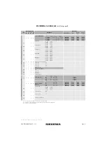
Page 2: ...M5 x 20 8 Slider 9 Key 10 Clamping piece EUL 11 Corner drive VSU 12 Striker 13 Slider MV 14 Tilt lock 15 Tilt locking part 16 Cheese head screw M5 x 12 17 Mishandling device LM 18 Coupling bracket LM...

Page 3: ...60 60 Flowdrill screw M4 x 20 317277 001 1 1 2 2 Bag accessories PSK PORTAL PMZJ0030 00001_ 8 2 2 4 4 Slider PFZJ0020 09901_ 9 1 1 2 2 Key PORTAL 719381 1 1 2 2 ZV LM PSK VAR SET MMZV0040 10001_ 10 3...

Page 4: ...g Cover cap set PSK LM PLUS PMZF0010 02501_ 00201_ 01201_ 26 1 1 2 2 Cover cap L right PKAF7011 02501_ 00201_ 01201_ 27 1 1 2 2 Cover cap L left PKAF7012 02501_ 00201_ 01201_ 28 1 1 2 2 Cover cap F ri...

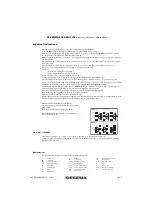
Page 5: ...resulting from insufficient tendering failure to follow these assembly instructions or force being applied to the fittings e g through improper use Hebelstellung PZ mit Hebel innen und au en Handle po...

Page 6: ...se Si line FAVORIT dark bronze for profile installation depth up to 73 mm 869833 1 Rose Si line FAVORIT white for profile installation depth up to 73 mm 862605 41 1 Removable handle Si line white for...

Page 7: ...x 12 20 Coupling bracket LM 21 Cover rail L 22 Connecting rod 23 Guiding rail 24 Cover rail F 25 Running rail 26 Cover cap L right 27 Cover cap L left 28 Cover cap F right 29 Cover cap F left 30 Stop...

Page 8: ...ary sashes must be labelled accordingly to prevent faulty operation The sliding sashes may be operated only in the order specified below To open main sash first 1 then secondary sash 2 To close second...

Page 9: ...der 8 d and turn 90 degrees 2 Pull stay arm down in direction of arrow e Note The stay arm safety device in the slider 8 may be opened only by using the SIEGENIA key 9 Unhinging the stay arms Sequence...

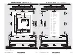
Page 10: ...H48 PSKLMS0001EN 22 11 2013 Page 11 16 21 5 14 2 1 4x RAH FH For vertical section bottom see page 16 Vertical section top PSK PORTAL 160 PLUS LM...

Page 11: ...Page 12 H48 PSKLMS001EN 22 11 2013 Page 13 RAB FB Scheme A Illustration shows DIN left DIN right is a mirror image of this illustration Horizontal section l PSK PORTAL 160 PLUS LM Horizontal section...

Page 12: ...Illustration shows DIN left DIN right is a mirror image of this illustration All dimensions in mm and specifications for Aluminium windows Euro groove in frame 10 to 14 mm Fitting cavity 21 1 mm For...

Page 13: ...orque 4 4 5 Nm H Insert stop body 31 and stop sleeve 32 into stop 30 according to sliding direction DIN left or DIN right I Insert stop 30 into running rail 25 and tighten slightly Note Do not securel...

Page 14: ...15 18 118 4x 5x Tragf hige durchgehende Unterf tterung der Laufschiene schon bei Beschlagmontage anbringen For vertical section top see page 11 Apply the lining to the running rail when assembling the...

Page 15: ...fsitz G2 350 min FH 3 22 21 1 Mark the middle of the sash and attach tilt stay accordingly observe markings 4 5 5 2 4 5 4 5 All dimensions in mm and specifications for Aluminium windows Euro groove in...

Page 16: ...op Couple Eckumlenkung VSU 11 with operating rod S3 and secure using clamping piece EUL 10 E Loosen coupling screw on Eckumlenkung VSU 11 Slide in Eckumlenkung VSU 11 vertically from below F Couple Ec...

Page 17: ...using flow drill screws M5 x 20 7 E Centre supporting piece L 34 for cover rail L 21 and screw on F Attach connecting rod 22 on bogie wheels V 2 mark off on marking from bo gie wheels H 3 and cut to...

Page 18: ...he tilt stay 8 Note Forhingingand unhinging the stay arms see page 10 SIEGENIA KG Hardware and ventilation technology Am Fohlengarten 6 54411 Hermeskeil Germany Tel 49 6503 917 0 Fax 49 6503 917 100 P...

Reviews: