background image


IV432E Rev.01 SIEL S.p.A. 


Installation and user manual 

Date of issue: 2021-05-05   


    Pag. 

45

  of 

50 

+ FR 

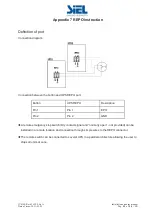
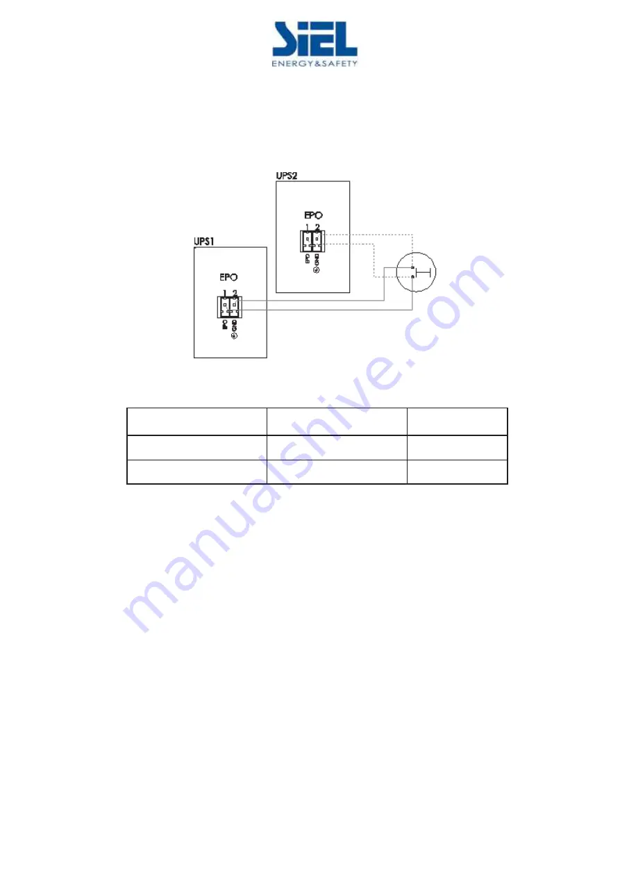
Appendix 7 REPO instruction 


Definition of port

͹


Connection diagram

͹


Connection between the button and UPS REPO port.   

Button 

UPS REPO 

Description 

Pin 1 

Pin 1 

EPO 

Pin 2 

Pin 2 

GND 


ƹ

A remote emergency stop switch (Dry contact signal and 

normally open

 - not provided) can be 

installed in a remote location and connection through simple wires to the REPO connector. 

ƹ

The remote switch can be connected to several UPS in a parallel architecture allowing the user to 

stops all units at once. 


Summary of Contents for SAFEPOWER S

Page 1: ...10 20kVA 3 1Ph UPS INTALLATION USER MANUAL SAFEPOWER S KEEP FOR FUTURE REFERENCE for the entire life of the appliance ...

Page 2: ... is an intelligent three phase in single phase out high frequency online UPS designed by our R D team who is with years of designing experiences on UPS With excellent electrical performance perfect intelligent monitoring and network functions smart appearance complying with EMC and safety standards The UPS meets the world s advanced level Read this manual carefully before installation This manual ...

Page 3: ...ntrol panel 10 3 4 Installation notes 11 3 5 External Protective Devices 11 3 6 Power Cables 12 3 7 Power cable connect 13 3 8 Battery connection 15 3 9 UPS parallel Installation 17 3 10 Computer access 18 4 Operation 20 4 1 Operation Modes 20 4 2 Turn on off UPS 22 4 3 The LCD Display 27 4 3 1 Home page 28 4 3 2 Running Information 30 4 3 3 Alarm 32 4 3 4 Setting 33 4 3 5 Advanced Setting 34 4 3 ...

Page 4: ...ns in this manual act as a supplementary for the local safety instructions Our company will not assume the liability that caused by disobeying safety instructions 1 1 Safety notes 1 Even no connection with utility power 220 230 240Vac voltage may still exist at UPS terminal 2 For the sake of human being safety please well earth the UPS before starting it 3ˊ Don t open or damage battery for the liq...

Page 5: ...uency fluctuation etc This UPS can be applied to different applications from computer device automatic equipment communication system to industry equipment 2 2 Functions and Features ƹDigital Control This series UPS is controlled by Digital Signal Processor DSP enhance it increases reliability performance self protection and self diagnostics and so on ƹBattery Configurable From 16 blocks to 20 blo...

Page 6: ...parameters such as input output voltage frequency load battery and ambient temperature etc ƹIntelligent Monitoring Function Via optional SNMP Card you may remotely control and monitor the UPS ƹEPO Function The series UPS may be completely shut off when the EPO is pressed REPO function Remote EPO is also available in this series UPS 3 Installation 3 1 Unpack checking 1 Don t lean the UPS when movin...

Page 7: ... p A Installation and user manual Date of issue 2021 05 05 Pag 7 of 50 FR 3 2 Cabinet Outlook 3 2 1 10 20k H Front View Side View 10kVA Rear View terminal block without cover 15 20kVA Rear View terminal block without cover ...

Page 8: ...ort 5 Dry contact port 6 External maintenance switch signal Maintenance switch cover plate 7 Maintenance switch 8 Output Switch 9 Terminal block for Input output battery Ground Dual input 10 Ground 11 Parallel port 1 12 Parallel port 2 13 Intelligent Slot 2 SNMP card Relay card 14 Intelligent Slot 1 SNMP card 15 RS485 port 16 REPO port 17 EVENTS port 18 Cold start button 19 Bypass Switch Dual inpu...

Page 9: ... 01 SIEL S p A Installation and user manual Date of issue 2021 05 05 Pag 9 of 50 FR 3 2 2 10 20k S Front View Side View 10kVA Rear View 15 20kVA Rear View terminal block without cover terminal block without cover ...

Page 10: ...nance switch signal Maintenance switch cover plate 7 Maintenance switch 8 Output Switch 9 Terminal block for Input output battery Ground Dual input 10 Ground 11 Parallel port 1 12 Parallel port 2 13 Intelligent Slot 1 SNMP card 14 Intelligent Slot 2 SNMP card Relay card 15 RS485 port 16 REPO port 17 EVENTS port 18 Cold start button 19 Bypass Switch Dual input 20 Power Switch 3 3 LCD control panel ...

Page 11: ...rmance data are quoted for an operating temperature between 20 C and 25 C Operating it above this range will reduce the battery life while operation below this range will reduce the battery capacity ƹShould the equipment not be installed immediately it must be stored in a room so as to protect it against excessive humidity and or heat sources CAUTION An unused battery must be recharged every 6mont...

Page 12: ...s and take into consideration the environmental conditions temperature and physical support media WARNING Upon starting Please ensure that you are aware of the location and operation of the external isolators which are connected to the UPS input bypass supply of the mains distribution panel Check to see if these supplies are electrically isolated And post and necessary warning signs to prevent any...

Page 13: ...ion Remove the cover of terminals for wiring easily Single input version Terminal sequence from left to right Input phase A L1 Input phase B L2 Input phase C L3 Input Neutral line Output phase Lo L1 Output Neutral line No Battery positive BAT Battery Neutral BATN Battery negative BAT There are 3 connectors of GROUND under the terminal block Dual input version Terminal sequence from left to right G...

Page 14: ...eater than or equal to that of the connection poles Input connection type Three phase in single phase out Single phase in single phase out WARNING If the load equipment is not ready to accept power on the arrival of the commissioning engineer then ensure that the system output cables are safely isolated at their ends Connect the safety earth and any necessary bonding earth cables to the copper ear...

Page 15: ...tery and the anode of the negative battery the BAT is connected to the cathode of the negative battery Factory setting of the long run unit is battery quantity 16pcs battery capacity 12V40AH charger current 6A When connecting 18 20 batteries please re set desired battery quantity and its capacity after UPS starts at AC mode Charger current could be adjusted automatically according to battery capac...

Page 16: ...d its capacity after UPS starts at AC mode Charger current could be adjusted automatically according to battery capacity selected All related settings can be done through LCD panel or monitoring software CAUTION Ensure correct polarity battery string series connection I e inter tier and inter block connections are from to terminals Don t mix batteries with different capacity or different brands or...

Page 17: ...battery and common battery WARNING Make sure the N A L1 B L2 C L3 lines are correct and grounding is well connected 3 9 2 Parallel cable installation Shielded and double insulated control cables available 5 meters standard length must be interconnected in a ring configuration between UPS units as shown below The ring configuration ensures high reliability of the control 3 9 3 Requirement for the p...

Page 18: ...ut cables and the UPS output cables should be the same This facilitates load sharing when operating in bypass mode 3 10 Computer access ƹOne end of a USB cable connect to the computer the other end connect to the USB port on the UPS ƹOpen the software Muser4000 click system button ƹA window of Software Parameter Setting comes out as below COM choose according to the UPS baud rate choose 9600 proto...

Page 19: ... Append then goes to a window of Append equipment ƹPut the UPS name into Equipment Name and UPS ID address into Equipment address ƹClick the button Append then the connection between UPS computer is accomplished CAUTION When the UPS worked on inverter If you want to use PC to set the output voltage and frequency Must shut down the inverter first ...

Page 20: ...supplies the critical AC load There is no power interruption to the critical load The UPS will automatically return to Normal Mode when AC recovers ƹBypass mode If the inverter is out of order or if overload occurs the static transfer switch will be activated to transfer the load from the inverter supply to bypass supply without interruption to the critical load In the event that the inverter outp...

Page 21: ... the UPS works at Line interactive mode so the UPS will transfer to bypass supply When the AC is out of set window the UPS will transfer from bypass to Inverter and supplies power from the battery and then the LCD shows all related information on the screen ƹMaintenance mode Manual Bypass A manual bypass switch is available to ensure continuity of supply to the critical load when the UPS is out of...

Page 22: ...er from the UPS make sure that it is safely isolated from the UPS output terminals ƹ Turn ON Bypass breaker Dual input version ƹ Turn ON Input breaker If the Rectifier input is within voltage range the rectifier will start up in 30 seconds then the inverter will start up after then ƹ Turn ON UPS output switch If the rectifier fails at startup the bypass LED will light up When the inverter starts u...

Page 23: ...al mechanical bypass system is active and the power is not conditioned Switch to mechanical bypass If the UPS is running normally and can be controlled through the display carry out steps 1 to 6 1 Open the cover of maintenance switch the UPS turns to bypass mode automatically 2 Turn on MAINTANCE breaker 3 Switch OFF BATTERY breaker 4 Switch OFF MAINS breaker 5 Switch OFF BYPASS breaker Dual input ...

Page 24: ...h ƹ Turn ON the power switch power will feed to auxiliary power board ƹ Trigger the cold start button as the position 18 of the below drawing When battery normal rectifier starts operation 30s later inverter starts and operates and battery LED on CAUTION Please press the cold start button after 30 seconds until closing the battery switch 4 2 5 Shut down procedure CAUTION This procedure should be f...

Page 25: ...located far away from the UPS area so a label should be posted to advise service personnel that the UPS circuit is under maintenance Battery mode ƹ Press OFF to shut down the UPS waiting about 30s ƹ Open the BATTERY breaker for long run UPS Open the battery power switch for standard UPS ƹ Switch OFF the OUTPUT breaker The UPS shuts down WARNING Wait for about 5 minutes for the internal D C bus bar...

Page 26: ... click Work Mode choose Parallel for the value then click Set as shown in below picture If the UPS sounds a beep that means the setting is correct ƹAt the window of Data Set click Ups ID write a value for the parallel UPS ID at the right side such as 1 then click Set as shown in below picture If the UPS sounds a beep that means the setting is correct ...

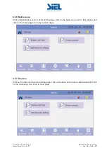
Page 27: ...ction described before CAUTION Parallel cable cannot be connected when setting the parallel parameters ƹAfter setting the UPS needed to be paralleled power off all the UPS Connect all the UPS according to parallel cable installation and then power on the UPS 4 3 The LCD Display Overview of the operating panel of the UPS 1 LED from top to bottom alarm bypass battery inverter 2 LCD display CAUTION T...

Page 28: ... 28 of 50 FR 4 3 1 Home page Show the UPS operating flow chart and there are the data entrance of input output battery 1 Click on the bypass icon to enter the bypass data window click on the back icon return to last window and click on the homepage icon jump to main page 20kVA 20kVA ...

Page 29: ...on the mains icon to enter the mains data window click on the back icon return to last window and click on the homepage icon jump to main page 3 Click on the Load icon to enter the output data window click on the back icon return to last window and click on the homepage icon jump to main page 20kVA 20kVA ...

Page 30: ...21 05 05 Pag 30 of 50 FR 4 Click on the battery icon to enter the battery data window click on the back icon return to last window and click on the homepage icon jump to main page 4 3 2 Running Information Click on Runn info icon to enter the information page 20kVA 20kVA ...

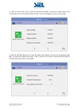
Page 31: ...w can see the breaker status click on the back icon return to last window and click on the homepage icon jump to main page 2 Click on the ENV data icon to enter the status data window can see the temperature data after connected to temperature sensor click on the back icon return to last window and click on the homepage icon jump to main page 20kVA 20kVA ...

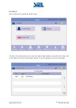
Page 32: ... 05 05 Pag 32 of 50 FR 4 3 3 Alarm Click on Alarm icon to enter the alarms page 1 Click on the active Alarm icon to enter the module data window can see the alarm data click on the back icon return to last window and click on the homepage icon jump to main page 20kVA 20kVA ...

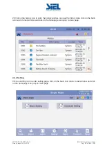
Page 33: ...tory icon to enter the histoty window can see the history data click on the back icon return to last window and click on the homepage icon jump to main page 4 3 4 Setting Click on setting icon to enter setting page click on the back icon return to last window and click on the homepage icon jump to main page 20kVA ...

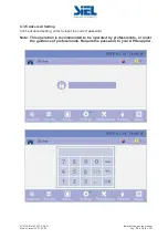
Page 34: ... issue 2021 05 05 Pag 34 of 50 FR 4 3 5 Advanced Setting Click advanced setting enter by input the correct password Note This operation is recommended to be operated by professionals or under the guidance of professionals Require the password to your UPS supplier ...

Page 35: ...nce Click on Maintenance icon to enter setting page click on the back icon return to last window and click on the homepage icon jump to main page 4 3 7 Function Click on Function icon to enter setting page click on the back icon return to last window and click on the homepage icon jump to main page 20kVA 20kVA ...

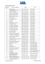
Page 36: ... lit 17 DC Bus Unbalance Beep continuously Fault LED lit 18 Soft Start Failed Beep continuously Fault LED lit 19 Rectifier Over Temperature Twice per second Fault LED lit 20 Inverter Over Temperature Twice per second Fault LED lit 21 Input Neutral Line Missing Twice per second Fault LED lit 22 Battery counter Twice per second Fault LED lit 23 Parallel Cable Connection Error Twice per second Fault ...

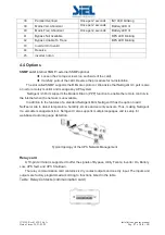
Page 37: ... to remotely monitor and manage any UPS system NetAgent II 3Ports supports the Modem Dial in PPP function to enable the remote control via the internet when the network is unavailable In addition to the features of a standard NetAgent Mini NetAgent II has the option to add NetFeeler Lite to detect temperature humidity smoke and security sensors Thus making NetAgent II a versatile management tool N...

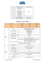
Page 38: ...tage Range Max voltage 220Vac 25 optional 10 15 20 230Vac 20 optional 10 15 240Vac 15 optional 10 Min voltage 45 optional 10 20 30 Frequency protection range 10 Generator Input Support Output Phase 220 230 240Vac L N PE Rated Voltage 220 230 240Vac Power Factor 1 0 Voltage Regulation 1 Frequency Utility Mode 1 2 4 5 10 of the rated frequency optional Battery Mode 50 60 0 1 Hz Crest Factor 3 1 THD ...

Page 39: ...st 5S 150 shut down UPS immediately Bypass Mode Breaker 64A Breaker 100A Breaker 126A Short Circuit 150A peak 270A peak 300A peak Overheat Line Mode Switch to Bypass Backup Mode Shut down UPS immediately Battery Low Alarm and Switch off Self diagnostics Upon Power On and Software Control EPO optional Shut down UPS immediately Battery Advanced Battery Management Noise Suppression Complies with EN62...

Page 40: ...utput breaker do not switch on Make sure the output cable is well connected Switch on the output breaker 4 Utility LED is flashing Utility voltage exceeds UPS input range If the UPS operates at battery mode please pay attention to the remaining backup time needed for your system 5 Battery LED is flashing but no charge voltage and current Battery breaker does not switch on or batteries are damaged ...

Page 41: ... USB port Description Pin 1 Pin 1 PC 5V Pin 2 Pin 2 PC DPLUS signal Pin 3 Pin 3 PC DMINUS signal Pin 4 Pin 4 Signal ground Available function of USB ƹ Monitor UPS power status ƹ Monitor UPS alarm info ƹ Monitor UPS running parameters ƹ Timing off on setting Communication data format Baud rate 9600bps Byte length 8bit End bit 1bit Parity check none CAUTION USB RS232 and RS485 interface cannot be us...

Page 42: ...PS RS232 port Pin 2 Pin 2 UPS send PC receive Pin 3 Pin 3 PC send UPS receive Pin 5 Pin 5 ground Available function of RS232 Monitor UPS power status Monitor UPS alarm info Monitor UPS running parameters Timing off on setting RS 232 communication data format Baud rate 9600bps Byte length 8bit End bit 1bit Parity check none CAUTION USB RS232 and RS485 interface cannot be used at the same time you c...

Page 43: ...Pin7 Pin7 12Vdc Pin8 Pin8 GND Available function of RS485 ƹ Monitor UPS power status ƹ Monitor UPS alarm info ƹ Monitor UPS running parameters ƹ Timing off on setting ƹBattery environment temperature monitoring ƹCharging voltage modulation depending on batteries temperature Communication data format Baud rate 9600bps Byte length 8bit End bit 1bit Parity check none CAUTION USB RS232 and RS485 inter...

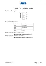
Page 44: ...Definition of Male port Instruction Relay Dry Contact Port 5A 277Vac UPS Instruction Pin1 Normally NC Pin2 Normally NO Pin3 Pin4 Common Function 1 description default internal J6 jumper ƹ Drive the bypass breaker when backfeed alarm Function 2 description Optional internal J5 jumper ƹ Drive the battery breaker when battery voltage low ...

Page 45: ...button and UPS REPO port Button UPS REPO Description Pin 1 Pin 1 EPO Pin 2 Pin 2 GND ƹA remote emergency stop switch Dry contact signal and normally open not provided can be installed in a remote location and connection through simple wires to the REPO connector ƹThe remote switch can be connected to several UPS in a parallel architecture allowing the user to stops all units at once ...

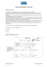
Page 46: ... source E g an isolation device can be a magnetic contactor The coil of the contactor should be supplied by eg fused L1 N voltage the input source in single mains configurations or by the bypass source in dual mains configurations via the output port as per Appendix 6 If the contactor coil exceeds the voltage current limits of the UPS output port a 24 Vcc source should be generated from the same s...

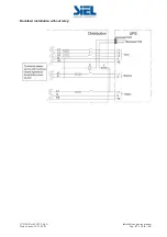
Page 47: ...IV432E Rev 01 SIEL S p A Installation and user manual Date of issue 2021 05 05 Pag 47 of 50 FR Backfeed installation without relay ...

Page 48: ...ight and left panel and then open both panels 2 Remove the battery connection wire Do not short the battery 3 Remove the screws of the covering of the battery and then remove the covering as the following picture shows Do not touch the battery terminals 4 Take out the battery that needs to be replace then install the new battery At last install the battery covering and connection wires ...

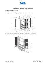
Page 49: ...f issue 2021 05 05 Pag 49 of 50 FR Appendix 10 Dust proof net replacement 10 20kVA replace the dust proof net Remove the screws of the right and left panel and then open both panels Remove the screws as the following picture shows and then remove the front panel ...

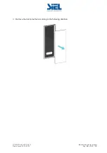
Page 50: ...IV432E Rev 01 SIEL S p A Installation and user manual Date of issue 2021 05 05 Pag 50 of 50 FR Remove the dust proof net according to the following direction ...

Reviews: