


Settings and add-on modules
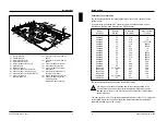
Primary CRT controller
You can set the primary CRT controller, by setting the jumper X180 to 6-15.
Color CRT controller = jumper X180 set to 6-15
Monochrome CRT controller = jumper X180 not inserted in 6-15
Default setting:
jumper X180 set to 6-15 = Color CRT controller
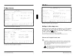
Processor
The jumper X180 8-17 always must be inserted. Depending on the processor type
inserted in socket D30, the jumpers X33 and X180 7-16 are inserted differently.
Socket D30
Jumper X33
Jumper X180 7-16
i486 SX, 25 MHz
1-2
---
i486 SX, 33 MHz
1-2
inserted
i486 DX/i486 DX2/OverDrive,
25 MHz / 50 MHz
2-3
---
i486 DX/i486 DX2/OverDrive,
33 MHz/66 MHz
2-3
inserted
--- = not inserted
A26361-D802-Z121-3-7619
23
Settings and add-on modules
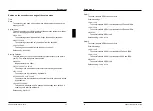
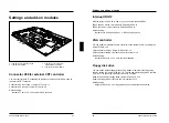
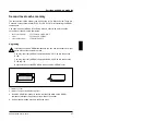
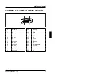
Upgrading
D30
1
2
1 = Mark on the socket
2 = Mark on the top of the processor
Remove the old processor from the socket.
Insert the new processor in such a way that the mark on the processor matches
the mark on the socket.
Set the jumpers X33 and X180 7-16 according to the inserted processor.
24
A26361-D802-Z121-3-7619


