


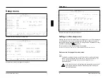

Setup menu
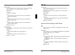
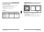
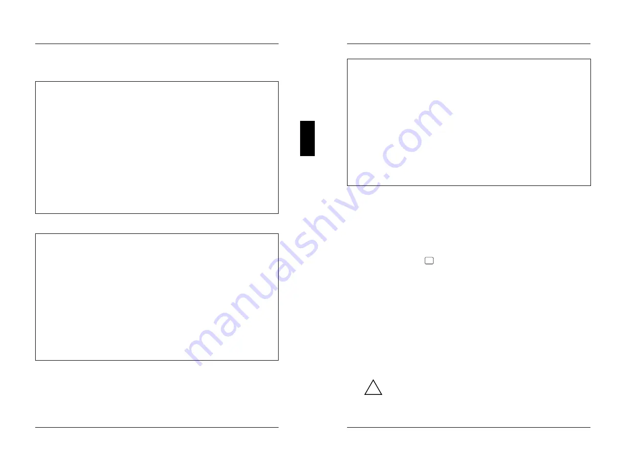
CMOS Setup
System Configuration
---------------------------------------------------------------------------
Time (hh:mm:ss) 08:38:27 Date (mm/dd/yyyy) 07/26/1993
Diskette A: 1.4M
Diskette B: NONE
Cyl Hd Pre LZ Sec Mbyte
Hard Disk 1: 48 904 8 NONE 904 46 162
Hard Disk 2: NONE
Base Memory: 640K Video Display: EGA/VGA
Extended Memory: 3072K Math Coprocessor: YES
Speed Select: HIGH
ERROR HALT: HALT ON ALL ERRORS
---------------------------------------------------------------------------
<F1> Help <F8> System info <F10> Store CMOS <Esc> Exit Page
<...> Edit field <
↑↓←→
> Next field <PgUp> Next page <Ctrl> ... 01
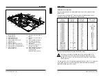
Example of the first screen page of a setup menu
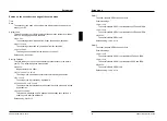
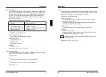
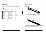
CMOS Setup
System Security Options
---------------------------------------------------------------------------
Time (hh:mm:ss) 08:38:27 Date (mm/dd/yyyy) 07/26/1993
System Load: STANDARD
Security Features: DISABLED
Serial 1: COM1 (3F8h) Diskette Write: ENABLED
Serial 2: COM2 (2F8h) Diskette Ctrlr: ENABLED
Parallel: LPT1 (378h) HD Ctrlr Mode: STANDARD
Par Mode: PRINTER HD Power Down: DISABLED
Hard Disk Ctrlr: ENABLED
Soft Power Off: DISABLED
---------------------------------------------------------------------------
<F1> Help <F8> System info <F10> Store CMOS <Esc> Exit Page
<...> Edit field <
↑↓←→
> Next field <PgUp> Next page <Ctrl> ... 02
Example of the second screen page of a setup menu
A26361-D802-Z121-3-7619
7
Setup menu
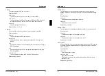
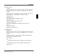
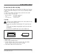
CMOS Setup
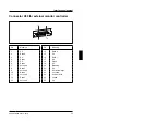
Additional System Options
---------------------------------------------------------------------------
Time (hh:mm:ss) 08:38:27 Date (mm/dd/yyyy) 07/26/1993
System BIOS: 64K
Shadow BIOS ROM: SYSTEM AND VIDEO BIOS
C800 CC00 D000 D400 D800 DC00
Shadow Adaptor ROM: NO NO NO NO NO NO
Cache:: INTERN AND EXTERN
Cache Shadow RAM:: VIDEO BIOS ONLY
C800 CC00 D000 D400 D800 DC00
Cache Adaptor ROM: NO NO NO NO NO NO
---------------------------------------------------------------------------
<F1> Help <F8> System info <F10> Store CMOS <Esc> Exit Page
<...> Edit field <
↑↓←→
> Next field <PgUp> Next page <Ctrl> ... 03
Example of the third screen page of a setup menu
Settings in the setup menu
Settings and technical information about the configuration of your PC are displayed
in the setup menu. How to call the setup menu and how to change the entries is
described in the Operating Manual of the PC. A help text can be obtained for every
input field by pressing the
F1
function key.
The setup menu consists of the following screen pages:
System Configuration
,
System Security Options
and
Additional System Options
.
Entries on the first page of the setup menu
Time
Date
The field
Time
defines the time of the PC, the field
Date
defines the date of
the PC. When changing the entries use for
Time
the entry format
hh:mm:ss
(hours:minutes:seconds) and for
Date
the entry format
mm/dd/yy
(month/day/year).
!
If the fields
DATE
and
TIME
are frequently wrong after you switch off
and on again, the battery is dead. Please apply in this case to the
customer field service.
8
A26361-D802-Z121-3-7619


