background image

Installing and removing a board


System unit

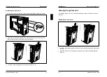
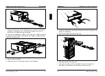
Removing a board

  Open the housing as described under "Opening the system unit".

  Remove the screw.

  Pull the board out of the slot.

  Place the board in its packaging.

!

For cooling, protection against fire and in order to comply with EMC
regulations, you must refit the rear slot cover plate.

A26361-K326-Z124-1-7619


17

System unit 

Installing and removing a board

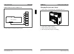
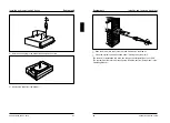
  Replace the rear slot cover plate. Ensure that the rear slot cover plate is

inserted between spring and slot.

  Fasten the rear slot cover plate with the screw you removed earlier.

  Close the housing as described in "Closing the system unit".

  Switch your PCE on.

  Start the EISA configuration program to reconfigure your PCE. How to configure

the system is described in the User Guide of the EISA configuration program.

18


A26361-K326-Z124-1-7619

Summary of Contents for D853

Page 1: ...rimé sur du papier recyclé Este manual ha sido impreso sobre papel reciclado Questo manuale è stato stampato su carta da riciclaggio Denna handbok är tryckt på recyclingpapper Dit handboek werd op recycling papier gedrukt Published by Siemens Nixdorf Informationssysteme AG 33094 Paderborn 81730 München Order No A26361 K326 Z124 1 7619 Printed in the Federal Republic of Germany AG 1194 11 94 A26361...

Page 2: ...ting Please contact the order number of the manual one of our IT Service Shops your sales partner Siemens Nixdorf Informationssysteme AG your sales office User Documentation Department BS2000 QM2 Otto Hahn Ring 6 You will find the addresses of the 81730 München Germany IT Service Shops in the enclosed warranty coupon booklet Fax 0 89 6 36 4 04 43 ...

Page 3: ...elfstudy material Please write or fax Siemens Nixdorf Informationssysteme AG Training Center Beratungsservice D 81730 München Fax 089 636 42945 Microsoft MS and MS DOS are registered trademarks and Windows is a trademark of Microsoft Corporation Copyright Siemens Nixdorf Informationssysteme AG 1994 All rights including rights of translation reproduction by printing copying or similar methods even ...

Page 4: ... the memory board 25 Installing memory modules 26 Removing memory modules 27 Installing the memory board 28 Installing and removing disk drives 29 Installing an accessible drive 29 Removing an accessible drive 34 Installing a non accessible drive 37 Removing a non accessible drive 40 Interrupts DMAs Interfaces 43 Interrupt and DMA assignment 43 Interrupt assignment 43 DMA assignment 43 Parallel in...

Page 5: ... before you install the system expansion Please read the section Copy update CFG files in the User Guide of the EISA Configuration Utility Explanation of symbols The meanings of the symbols and fonts used in this manual are as follows Pay particular attention to texts marked with this symbol They always contain important information This symbol is followed by supplementary information remarks and ...

Page 6: ...ly unit marked with a lightening flash symbol should be removed and replaced only by authorized specialists If your PCE is equipped with a power outage fallback facility the battery block should be removed and replaced only by authorized specialists Due to the danger of injury or electric shock do not remove the rear part of the casing The warranty expires if the PCE is damaged during the installa...

Page 7: ...ting you pull out the connectors on the system unit Unlock the cover at the rear of the system unit A26361 K326 Z124 1 7619 5 System unit Opening the system unit 1 2 Remove the cover at the rear of the system unit 1 2 Pull out the connectors at the back of the system unit Removing top cover and side covers Lift off the top cover 6 A26361 K326 Z124 1 7619 ...

Page 8: ...ng it upward at a slanting angle Ensure that the two side covers are not confused A26361 K326 Z124 1 7619 7 System unit Opening the system unit If you want to install or remove boards e g expansion memory or processor boards you must also remove the plastic side cover 1 S1 2 If exist pull the loudspeaker plug on the connection board 1 Release the SCSI cable from the plastic cover 2 1 2 Release the...

Page 9: ...1 2 2 Pull off the front cover upward at an slanting angle 1 2 A26361 K326 Z124 1 7619 9 System unit Closing the system unit Closing the system unit To close the system unit you must first replace the front cover if they have been removed Replacing the front cover 1 2 1 Insert the lower plastic guides of the front cover into the openings in the system unit 1 Move the front cover up against the sys...

Page 10: ...nto the connection board 1 Attach the SCSI cable to plastic cover 2 A26361 K326 Z124 1 7619 11 System unit Closing the system unit Ensure that the two side covers are not confused when they are installed 3 2 1 Drop the side cover into the groove at a slanting angle 1 Push the side cover up against the system unit 2 and lift the extensions of the cover over the housing slots Ensure that no cables a...

Page 11: ... press it down into place Position the system unit at your workstation Plug in the cables of all units that were connected to the system unit 2 1 Fasten the cover plate at the back of the system unit A26361 K326 Z124 1 7619 13 System unit Closing the system unit Lock the cover plate at the back of the system unit Insert the power plug 14 A26361 K326 Z124 1 7619 ...

Page 12: ...your board out of its packaging A26361 K326 Z124 1 7619 15 System unit Installing and removing a board Push the board horizontally up against the system board at the rear Ensure that the metal bracket of the board is inserted between spring and slot Carefully press board into the slot Fasten the board in position with the screw you removed earlier Close the housing as described in Closing the syst...

Page 13: ...ver plate A26361 K326 Z124 1 7619 17 System unit Installing and removing a board Replace the rear slot cover plate Ensure that the rear slot cover plate is inserted between spring and slot Fasten the rear slot cover plate with the screw you removed earlier Close the housing as described in Closing the system unit Switch your PCE on Start the EISA configuration program to reconfigure your PCE How t...

Page 14: ... drives if available on DAC Bay 6 5 4 1 2 3 SCSI ID 0 resistor installed SCSI ID 1 resistor not installed SCSI ID 1 resistor not installed SCSI ID 1 resistor not installed SCSI ID 0 resistor installed SCSI ID 0 resistor installed Channel 0 Channel 1 Channel 2 Disk Array Controller Communicationchannel Channel 0 Overview allocation of slot SCSI ID SCSI channel and terminating resistor A26361 K326 Z...

Page 15: ...lled SCSI ID 2 resistor not installed SCSI connector SCSI Controller Overview allocation of slot SCSI ID and terminating resistor A26361 K326 Z124 1 7619 21 System unit Changing the processor board Changing the processor board Open the system unit as described under Opening the system unit Pull the processor board out of the slot Place the processor board in its packaging Take the new processor bo...

Page 16: ...o 512 Mbytes by using 32 Mbyte modules 1 1 memory bank The memory board has 16 sockets for memory modules SIMM Single In line Memory Modules PS 2 modules which are divided into 8 memory banks with 2 sockets each Memory modules have a capacity of either 8 or 32 Mbytes A memory bank must always be fully occupied and equipped with memory modules of the same capacity Thus a memory capacity of 16 or 64...

Page 17: ...lling memory modules make sure that the memory modules already installed do not hinder the installation of subsequent modules Insert the first memory module into its slot from the back at an angle of about 45 Tilt the module carefully to the front until it snaps into place and is in a vertical position in the socket Check that the memory module is securely in place in its socket The notches on the...

Page 18: ...ward using the tabs Tilt the memory module to the back and pull it out of its socket A26361 K326 Z124 1 7619 27 System unit Installing and removing memory modules Repeat the steps for the second module of the memory bank for the removal of modules of other memory banks Installing the memory board Slide the memory board into the guides until it is up against the system board Carefully press the mem...

Page 19: ... standard the terminating resistor is plugged in at the hard disk installed in the lowest bay ID 0 The address of the installed hard disk ID 0 must not be modified since the system BIOS requires this address for booting the system Installing an accessible drive SCSI drives in bays 1 4 may not have terminating resistors Open the system unit as described under Opening the system unit Select an insta...

Page 20: ...the outside e g floppy disk drive CD ROM or not hard disk Place the drive in the drawer Screw down the drive in accordance with the type of installation A26361 K326 Z124 1 7619 31 System unit Installing and removing disk drives Connect the data cable to the drive Ensure that the connector is plugged in the right way round coding Plug the power supply connector into the drive Slide the drawer into ...

Page 21: ...tal plate A plastic cover is inserted into this metal plate and replaces the cover now missing in the front cover Both parts metal plate and plastic cover are obtainable as an F set quoting the order number S26361 F1031 L1 Close the housing as described under Closing the system unit The removal or installation of a drive can change the configuration of your PCE The system must therefore be reconfi...

Page 22: ... plate A plastic cover is inserted into this metal plate and replaces the cover now missing in the front cover Both parts metal plate and plastic cover are obtainable as an F set quoting the order number S26361 F1031 L1 Slide the drawer into the system unit and screw down the drawer plus metal plate s Close the system unit as described under Closing the system unit The removal or installation of a...

Page 23: ... has a terminating resistor Select a bay Unscrew the screws Pull the drawer out of the system unit The motor of a SCSI drive is started by the BIOS using a software command on booting The drive must therefore be so adjusted that its motor does not start up as soon as the PCE is switched on The documentation for your drive will tell you whether you have to adjust the drive Make the necessary adjust...

Page 24: ...stallation of a drive can change the configuration of your PCE The system must therefore be reconfigured Read the section Setup menu in the Operating Manual A26361 K326 Z124 1 7619 39 System unit Installing and removing disk drives Removing a non accessible drive Open the system unit as described under Opening the system unit Pull the data and power supply connectors from the drive you wish to rem...

Page 25: ...em unit Installing and removing disk drives Slide the drawer into the system unit and screw down the drawer Close the system unit as described under Closing the system unit The removal or installation of a drive can change the configuration of your PCE The system must therefore be reconfigured Read the section Setup menu in the Operating Manual 42 A26361 K326 Z124 1 7619 ...

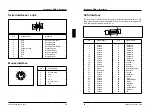
Page 26: ...5 SCSI controller 2 The interrupts 10 11 14 and 15 can be programmed in the Setup menu DMA assignment DMA 0 free DMA 1 free DMA 2 Floppy disk controller DMA 3 free DMA 4 free DMA 5 free DMA 6 free DMA 7 free A26361 K326 Z124 1 7619 43 Interrupts DMAs interfaces Parallel interface Centronics 1 13 25 14 Pin Signal name Meaning 1 STROBE Data message 2 9 Data Lines 0 7 Data lines 0 7 10 ACKNOWLEDGE Da...

Page 27: ...ble connecting system board and SCSI drive is a color coded 50 wire standard SCSI cable with a maximum length of 3 m 1 25 26 50 Pin Signal name Pin Signal name 1 Ground 2 Data bit 0 3 Ground 4 Data bit 1 5 Ground 6 Data bit 2 7 Ground 8 Data bit 3 9 Ground 10 Data bit 4 11 Ground 12 Data bit 5 13 Ground 14 Data bit 6 15 Ground 16 Data bit 7 17 Ground 18 Data parity 19 Ground 20 Ground 21 Ground 22...

Page 28: ...itional signals of the 8 Real time clock battery buffered system control board 9 Jumper for terminating resistor SCSI interface 1 A26361 K326 Z124 1 7619 47 Boards System board Configuration options for the EISA slots EISA slot Master and Slave Slave only 1 x 2 x 3 x 4 x 5 x 6 x 7 x 8 x Terminating resistor for SCSI interface 1 Jumper 9 on the system board is provided for setting the terminating r...

Page 29: ...a terminating resistor If SCSI drives are connected to SCSI interface 2 of the connection board the terminating resistor on the connection board must be deactivated i e switch S1 must be opened The last SCSI drive connected to SCSI interface 2 on the connection board must have a terminating resistor A26361 K326 Z124 1 7619 49 Boards Connection board SCSI interface 2 on the connection board is not ...

Page 30: ... H J K L X C V B N Alt Gr Alt 1 2 3 é è ç à Z Y A Q M ù W Ctrl Ctrl µ Entrée A26361 K326 Z124 1 7619 51 Keyboard labeling GERMANY 1 2 3 4 5 6 8 9 0 ß Q W E R T Z U I O P Ü 2 3 7 A S D F G H J K L Ö Ä Y X C V B N M µ Strg Alt Gr Alt Strg ITALY 1 2 3 4 5 6 8 9 0 Q W E R T U I O P 7 A S D F G H J K L X C V B N M Alt Gr Alt Y Z Ctrl Ctrl Caps Lock é è ç ò à ù Invio ì NORWAY 1 2 3 4 5 6 8 9 0 Q W E R T...

Page 31: ...K L Y X C V B N M Alt Gr Alt Ç è ü ü è é é ö ö à à ä ä Ctrl Ctrl Caps Lock Enter A26361 K326 Z124 1 7619 53 Keyboard labeling SPAIN 1 2 3 4 5 6 8 9 0 Q W E R U I O P 7 A S D F G H J K L X C V B N M Alt Gr Alt ª º Z Ñ Ç Bloq Mayús Control Control T Y U K 1 2 3 4 5 6 8 9 0 Q W E R U I O P 7 A S D F G H J K L X C V B N M Alt Gr Alt Z T Y Caps Lock Ctrl Enter Ctrl U S 1 2 3 4 5 6 8 9 0 Q W E R T U I O...

Page 32: ... removing 29 SCSI interface 46 Disk drives bays 29 A26361 K326 Z124 1 7619 55 Index DMA 43 I assignment 43 I O SCSI interface 46 channel 43 ID SCSI drive 29 Drive Identification number SCSI drive 29 connecting 32 Important notes 3 installing 37 INIT parallel interface 44 DSR serial interface 45 Initialize parallel interface 44 DTR serial interface 45 Installing a board 15 E accessible drive 29 EIS...

Page 33: ... 1 48 interrupt 43 controller 2 49 50 Rear slot cover plate 15 17 terminating resistor 49 Receive Data serial interface 45 controller interrupt 43 Removing SCSI drive a board 15 17 installing 37 an accessible drive 34 motor start up 37 disk drive 29 terminating resistor 29 front cover 9 SCSI hard disk drive 40 ID 29 memory interface 47 board 25 interface 1 terminating resistor 48 module 27 interfa...

Page 34: ...nating resistor 29 SCSI controller 2 49 drive 29 interface 1 48 interface 2 50 Terminator power SCSI interface 46 Timer interrupt 43 Top cover removing 6 replacing 11 Transmit Data serial interface 45 TxD serial interface 45 U Unlock 5 V V 24 interface interface assignment 45 VESA slot local bus 47 VGA controller interrupt 43 W Warranty 5 A26361 K326 Z124 1 7619 59 ...

Reviews: