Advanced
Settings in BIOS Setup
Audio Controller
sets the base address for the audio controller on the system board or disables the
audio controller.
220h, 240h, 260h, 280h
The audio controller is set to the corresponding base address.
Simultaneously one of the interrupts IRQ 5, IRQ 7, IRQ 9 or IRQ 10
is used. Which interrupt is used is defined by the audio driver
software (default entry).
Disabled
The audio controller is disabled, and does not occupy an interrupt.
Game Port
Requirement: The
Audio Controller
field is set to
220h
,
240h
,
260h
or
280h
.
This field is used to enable and disable the game port on the system board.
Enabled
The game port is enabled (default entry).
Disabled
The game port is disabled.
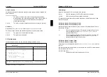
PCI Configuration
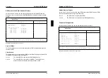
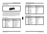
calls a submenu in which you can make the settings for the PCI slots.
Phoenix BIOS Setup Copyright 1985-94 Phoenix Technologies Ltd.
Advanced
PCI Configuration Item Specific Help
VGA Interrupt: [Enabled]
PCI Device, Slot #1
Default Latency Timer: [Yes]
Latency Timer: [0040]
PCI Device, Slot #2
Default Latency Timer: [Yes]
Latency Timer: [0040]
F1 Help
↑↓
Select Item -/+ Change Values F9 Setup Defaults
ESC Exit
←→
Select Menu Enter Execute Command F7 Previous Values
Example for submenu
PCI Configuration
A26361-D858-Z120-6-7619
23
Settings in BIOS Setup Advanced
VGA interrupt
assigns an available PCI VGA controller to the interrupt.
Enabled
IRQ 9 is assigned to the PCI VGA controller (if it exists).
Disabled
IRQ 9 can be used for other add-on modules.
To enable a change to take effect, exit the Setup menu, switch the device off and
then back on again.
PCI Device, Slot #1: Default Latency Timer
PCI Device, Slot #2: Default Latency Timer
specifies the lowest number of clock cycles in which a PCI master module can be
active at the PCI bus.
Yes
The value predefined by the PCI module is accepted. The entry in
the corresponding field for
PCI Device, Slot #n: Latency Timer
is
ignored (default entry).
No
The value predefined by the PCI module is ignored. The value set
in the corresponding field for
PCI Device, Slot #n: Latency Timer
determines the number of clock cycles.
PCI Device, Slot #1: Latency Timer
PCI Device, Slot #2: Latency Timer
Requirement: the corresponding field for
PCI Device, Slot #n: Latency Timer
must be
set to
No
.
The field specifies the lowest number of clock cycles in which a PCI master module
can be active at the PCI bus.
0000h
through
0280h
Number of clock cycles (default entry =
0040h
).
24
A26361-D858-Z120-6-7619


