background image

Fume Hood Controller Owner's Manual 

12 


Siemens Building Technologies, Inc. 

Basic Operation 

The Fume Hood Controller provides Direct Digital Control (DDC) technology for controlling 
fume hood face velocities in a manifolded fume hood exhaust system. 

High and Low Exhaust Flow Control 

The Fume Hood Controller can operate at two different setpoints, described as HI flow and 
LOW flow setpoints. The low setpoint can be set to zero to send the controller into an OFF 
mode. The OFF mode shuts off the flow alarms and closes the exhaust flow control device 
and allows the controller to go into a standby mode of operation. 

The Operators Display Panel (ODP) can display HI/LOW setpoint or output exhaust flow in 
CFM. Due to display limits, the actual number displayed is CFM divided by 10. 

Control Loops 

The PID loop controls the exhaust flow control device based on the values of the exhaust 
flow and the flow setpoint. The loop output controls the supply and exhaust through a time 
modulation scheme. The control loopout ranges from -100 to 100%. 


-100% is the maximum supply that closes the exhaust flow control device at full 
speed. 


0% holds the exhaust flow control device at its current position. 


100% is the maximum exhaust that opens the exhaust flow control device at full 
speed. 


Electronic 

The controller sends a separate signal to each of the two inputs that reside on the AO-E 
module. For values of 100% to 0%, the controller sends a decreasing percentage of the full 
signal length to the retract input. For values of 0% to -100%, the controller sends an 
increasing percentage of the full signal to the extend input. 

Pneumatic  

The controller sends a separate signal to each of the two solenoids that reside on the AO–P 
module. For values of 100% to 0%, the controller sends a decreasing percentage of the full 
signal length to the exhaust solenoid. For values of 0% to -100%, the controller sends an 
increasing percentage of the full signal length to the supply solenoid. 

Calibration 

Air Velocity Sensor -

 Calibration of the controller's air velocity sensor is periodically required 

to maintain accurate air velocity readings. 

Summary of Contents for 125-5033

Page 1: ...Two State Constant Volume Fume Hood Controller Owner s Manual 125 5033 Rev AA September 2007 ...

Page 2: ......

Page 3: ...in which case users at their own expense will be required to take whatever measures may be required to correct the interference SERVICE STATEMENT Control devices are combined to make a system Each control device is mechanical in nature and all mechanical components must be regularly serviced to optimize their operation All Siemens Building Technologies branch offices and authorized distributors of...

Page 4: ......

Page 5: ...1 Electronic Actuation 1 Pneumatic Actuation 1 Ordering Notes 2 Hardware Inputs 3 Analog 3 Digital 3 Hardware Outputs 3 Analog 3 Digital 3 Power Wiring 3 Communication Wiring 3 Controller LED Indicators 4 Operator Display Panel ODP 4 Laboratory Exhaust Air Terminal 5 Venturi Air Valves 6 Electronic Actuator Assembly Err or Bookmark not defined Pneumatic Actuator 8 Analog Output Pneumatic AO P Modu...

Page 6: ...rning Operation 13 Alarm Operation 13 Alarm Strategies 14 Emergency Purge Feature 14 Emergency Purge Operation 14 Emergency Purge Strategies 15 Fail safe Operation 16 Fume Hood Controller 16 ODP 16 Differential Pressure Transmitter 16 Electronic Actuator Assembly 16 Pneumatic Actuator 16 AO P Module 16 Point Database 17 Troubleshooting 20 Basic Service Information 20 Preventive Maintenance 20 Safe...

Page 7: ...ller Chapter 3 Point Database defines the point database descriptors and includes address and applications The Glossary describes terms and acronyms The Index helps you find information Manual Conventions The following table lists conventions used in this manual Convention Example Actions that you should perform are specified in boldface font Type F for Field panels Click OK to save changes and cl...

Page 8: ...re and edit any APOGEE database but only Datamate Advanced allows you to edit points offline Backing up and restoring a database can be accomplished while connected to any APOGEE field panel or to the Building Level Network BLN or Floor Level Network FLN device in question A modem and telephone lines can also be used Databases can be saved to a hard or floppy disk and kept for permanent storage or...

Page 9: ...d Figure 1 is the central computing controlling component of the system Related Equipment Operator Display Panel ODP Laboratory Exhaust Air Terminal Venturi Air Valve Differential Pressure Transmitter See NOTE Airflow Sensor See NOTE Cables Electronic Actuation Electronic Actuator Assembly See NOTE Pneumatic Actuation Analog Output Pneumatic AO P Module See NOTE Pneumatic Actuator See NOTE NOTE Th...

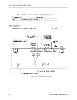
Page 10: ...uilding Technologies Inc Table 1 Fume Hood Controller Electronic Output Applications Application Description 940 2 Position Fume Hood Controller Ordering Notes Fume Hood Controller Electronic Output 940 546 00750 Figure 1 Fume Hood Controller Board ...

Page 11: ...communications trunk DO3 24 Vac Alarm Hi Low Output Power Wiring The controller is powered by 24 Vac Power wiring connects to the three screw terminals on the controller labeled C Common H Hot and E Ground on the terminal block labeled TB1 Earth ground connection is required Figure 2 Communication Wiring The controller connects to the field panel by means of a Field Level Network FLN trunk Communi...

Page 12: ...t BST Indicates when flashing ON and OFF once per second that the controller is functioning properly Operator Display Panel ODP The Operator Display Panel ODP is the interface device between the Fume Hood Controller and the operator Its main functions are to display normal warning and alarm conditions to the operator The ODP consists of a housing three Light Emitting Diodes LEDs a liquid crystal d...

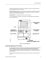
Page 13: ...not used currently For more information on the ODP see the Fume Hood Controller Operator Display Panel User s Card 125 1976 Figure 4 Operator Display Panel Laboratory Exhaust Air Terminal The Laboratory Exhaust Air Terminal is a pre packaged easy to install airflow measurement and control station See Figure 5 It combines an orifice plate flow sensor differential pressure transmitter an electronic ...

Page 14: ... gauge steel for highly corrosive environments Figure 5 Laboratory Exhaust Air Terminal Venturi Air Valves The Venturi Air Valve is a pre packaged easy to install airflow measurement and control station See Figure 6 This assembly combines the orifice plate flow sensor differential pressure transmitter Electronic actuator and a Venturi Air Valve This arrangement provides fast acting stable and prec...

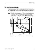
Page 15: ...tor assembly is used because of its small size and quick response time CAUTION Due to the design parameters and the response time required by the Fume Hood Controller the assembly must be replaced with the same part or a Siemens Building Technologies Inc approved equivalent Any modifications that are not approved may affect the safety and performance of the Fume Hood Controller 1 1 1 11 75 14 5 AO...

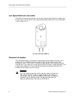
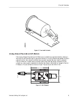
Page 16: ...tic actuator Figure 8 used with the Fume Hood Controller is the No 3 unit The No 3 actuator is used because of its small size and quick response time The actuator has a deep drawn aluminum housing a rubber diaphragm and a spring return rated at 8 to 13 psi Pneumatic actuation requires two components the actuator and the transducer AO P module WARNING Due to the design parameters and the response t...

Page 17: ...es electrical signals from the Fume Hood Controller into pneumatic signals that command the actuator The AO P Module consists of two industrial grade solenoids that supply or bleed air to the actuator by using a pulse modulation technique See Figure 9 Minimum air supply to the AO P Module is 18 psi and the maximum is 30 psi The valves are rated for 24 Vac 5 00 127 0mm 3 70 94 0mm SUPPLY COMMON EXH...

Page 18: ...lt Siemens Building Technologies for more information about a comprehensive laboratory ventilation system evaluation and associated test programs Airflow Sensor Airflow sensors are used in conjunction with the differential pressure transmitter The airflow sensor senses an average air velocity across the duct section Using the average air velocity and the duct area the controller calculates the air...

Page 19: ...tem In this application two position fume hoods have an individual exhaust damper or venturi air valve connected to a central fan The application modulates the exhaust flow control device to maintain a high or low flow setpoint based on inputs from the ODP Operators Display Panel Digital Input an exhaust airflow sensor and the controller setpoints Figure 10 Figure 10 Application 940 Control Drawin...

Page 20: ...exhaust through a time modulation scheme The control loopout ranges from 100 to 100 100 is the maximum supply that closes the exhaust flow control device at full speed 0 holds the exhaust flow control device at its current position 100 is the maximum exhaust that opens the exhaust flow control device at full speed Electronic The controller sends a separate signal to each of the two inputs that res...

Page 21: ...rmation Consult your local Siemens Building Technologies Inc representative for more information on central alarming Warning Operation The Fume Hood Controller announces warning conditions at the ODP The ODP indicates a warning condition by illuminating the yellow LED If the fume hood is operating and the exhaust volume exceeds the high or low warning limit for a period greater than the delay time...

Page 22: ... hood user to override normal airflow setpoint and temporarily increase the airflow beyond the value needed to maintain the airflow setpoint The Emergency Purge overrides any other control mode in the Fume Hood Controller and has two modes of operation maximum purge and controlled purge The maximum purge moves the exhaust airflow control device to full open and holds it there regardless of airflow...

Page 23: ...e capacity of the central exhaust system If the maximum purge mode is selected the emergency timer and the emergency setpoint to their maximum values If the controlled purge mode is selected the emergency timer is set to 0 Select the value for the emergency setpoint to indicate how much you want the emergency airflow to increase over the normal airflow For example if your emergency procedures call...

Page 24: ...ls to both the exhaust fan and the controller there will be no indication except for the absence of the noise that the air makes during normal operation ODP If the ODP fails the controller will continue to control the fume hood face velocity However no display or audible alarming will be available Differential Pressure Transmitter If the differential pressure transmitter fails the controller will ...

Page 25: ...tor presses the EMERGENCY PURGE button the point is ON the red LED is illuminated the alarm sounds and EEE and EMERGENCY MODE display at the ODP If pressed again then the point is OFF This point can be commanded by a field panel 08 GEN FAILURE Indicates a hardware failure e g the pressure sensor with an ON or OFF status The red LED is illuminated the alarm sounds and FFF and GENERAL FAILURE displa...

Page 26: ...re transmitter Standard values are 0 1 25 3 0 25 62 275 0 5 124 55 and 1 0 253 35 EXH FLOW The calculated value in CFM LPS of the exhaust airflow as measured with the differential pressure transmitter sensor 36 FLOW COEFF Gain factor for the flow sensor 37 FLOW STPT Setpoint in CFM LPS that the airflow is controlled to 38 FLOW LO STPT The low flow setpoint used in FLOW STPT 40 CAL DP TRANS YES or ...

Page 27: ...BLE the audible alarm will not sound All other alarm functionality is still operational 91 BLANK DSPLY When set to YES the exhaust flow is not displayed at the ODP 92 DO2 INVERTER Setting to NCLOSE allows the controller to operate industry standard floating control actuators Setting this point may stop the failsafe operation from functioning 93 ENG UNITS Toggles the display of the ODP from CFM to ...

Page 28: ...OFF the power to the 24 Vac transformer The recommended method of removing power to a controller on a power cable even to service a single controller is to turn OFF the power at the transformer NOTE When removing power to a controller to perform maintenance or service make sure that the person in charge of the facility is aware of this and that appropriate steps are taken to keep the building in c...

Page 29: ...and are used by the controller unless overridden by a field panel Controller LEDs To determine if the controller is powered up and working verify that the Basic Sanity Test BST Light Emitting Diode LED is flashing ON OFF once per second The controller contains six LEDs located on the circuit board See the Controller LED lndicators section of Chapter 1 Product Overview for more information about LE...

Page 30: ...point is a physical point which accepts a continuous variable signal algorithm Mathematical formula used to calculate an output value using varying inputs centralized control The type of control offered by a controller that is connected by means of a Floor Level Network FLN with an APOGEE field panel control loop A PID algorithm which is used to control an output based on a setpoint and an input r...

Page 31: ... reports displays and warnings FLN Field Level Network formerly known Floor Level Network Fume Hood Controller Multi application equipment controller designed to provide Direct Digital Control for various types of Variable Air Volume VAV fume hoods The controller consists of a controller board and a controller enclosure intercept Factor which converts analog values used by the controller to a form...

Page 32: ...quipment Controllers RTS Room Temperature Sensor sash sensor actuator Device that rides along the sash sensor strip to vary the resistance reading to the Fume Hood Controller SI units Systeme International d Unites The international metric system slave mode Default application that comes up when power is first applied to a Terminal Equipment Controller slope Factor which converts analog values use...

Page 33: ...lding Technologies Inc product family of equipment controllers one is the Unit Conditioner Controller Electronic Output that house the applications software used to control terminal units such as heat pumps VAV terminal boxes fan coil units unit ventilators etc UNOCC mode UNOCCupied mode ...

Page 34: ...hooting 22 D DDC see Direct Digital Control DI see digital input differential pressure transmitter 9 digital input 2 digital output 2 Direct Digital Control 1 10 DO see digital output E electronic actuation 1 electronic actuator damper 7 emergency purge 12 controlled purge 12 lab workers 13 maximum purge 12 operation 12 safety officer 13 strategies 13 emergency purge button 4 F fail safe operation...

Page 35: ...neumatic actuator damper 7 pneumatic damper actuator see damper actuator point database 18 power loss 14 power wiring 3 4 product overview ordering 2 R related equipment 1 RJ 11 connector 9 RX LED 23 S service information basic 22 static discharge 22 T troubleshooting basic service information 22 controller 22 TX LED 23 V VA rating 2 W warning and alarms 10 alarm operation 11 alarm strategies 11 w...

Reviews: