background image

3.6

Removing / Fitting the motor rotor

including bearing replacement

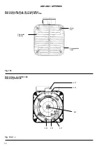
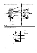
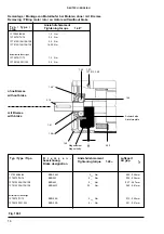
Removing (see Fig. 109.1, 109.2)
- Mark position between endshields on housing
- Remove nuts (1.97) or screws in the case of 1FT5 13. (1.49) from D-

end endshield (1.40)

- Carefully pull motor rotor (3.10) together with D-end endshield out of

motor stator (4.00)
NOTE: When rotor is removed, protect from contamination with magnetic
waste (plastic bag)

- Release screws (1.48) and remove D-end endshield
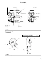
- Pull off D-end bearing (1.60) and sleeve (1.41) with suitable tool (see

Fig. 109.2), heat sleeve to approx. 180°C to reduce the effect of the
adhesive

- Pull off N-end bearing

Fitting
- Fit new D-end and N-end bearings on motor shaft, making sure that the

D-end bearing fits in the centring hole of the bearing cover (1.44)
NOTE:  We recommend that the roller bearings be heated evenly to
approx. 80-100°C for fitting purposes; never strike the bearings violently
(e.g. with a hammer)

- Apply adhesive (e.g. Loctite 243) to the inside of the sleeve (1.41) and

push onto the shaft as far as the shoulder - on motors with safety rating
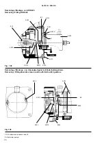
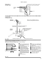
IP 67, the adhesive must form a sealIf fitting a radial shaft seal (IP 67),
refer to Fig. 110
We recommend that the sleeve (1.41) is replaced on motors with a radial
shaft seal (1.42)

- Fix bearing cover with screws (1.48), tighten to specified torque (see

Fig. 109.1)

- Insert motor rotor with D-end endshield into the motor stator and fix to

stator

3.7

Removing/Fitting motor rotor including

bearing replacement on motor with brake

NOTE: In principle it is possible to replace or fit a fail-safe brake at a later
date, however, the modification should only be done by a SIEMENS
Service Center.

3.7.1 Removing the brake connections

Terminal box
- Remove terminal box cover
- Release brake connecting leads from terminal box. Cut off end lug on

brake connecting lead

Connector size 1 (see Fig. 109.2)
- Unscrew connector (5.100)
- By releasing the catch (V) and pressing towards the insulator at the

same time, remove insulator from housing

- Remove pin contacts for pins 4 and 5 for brake connections using

removing tool (see SIMODRIVE accessories)

- Cut off brake connecting leads at the contacts

Connector sizes 2 and 3
- Unscrew connector cover
- Release screws for brake connections and cut off lugs

3.7.2 Removing/Fitting motor rotor with D-end

and N-end bearings

Removing (see Fig. 109.1, 109.2)
- Mark position between endshields on housing
- Remove nuts (1.97) or screws in the case of 1FT5 13. (1.49) from D-

end endshield (1.40)

- Carefully pull motor rotor (3.10) together with D-end endshield out of

motor stator (4.00) - be careful not to damage brake connecting leads
NOTE: When rotor is removed, protect from contamination with magnetic
waste (plastic bag)

- Release screws (1.48) and remove D-end endshield
- Pull off magnet body and brake connecting leads together with D-end

bearing (1.60) and sleeve (1.41) with suitable tool (see Fig. 109.2), heat
sleeve to approx. 180°C to reduce the effect of the adhesive
NOTE: Before pulling off the magnet body, the brake must be energized
(24 V DC ± 10%, check for correct polarity) so that the brake is released
and the diaphragm springs are not overstressed

- Pull off N-end bearing

Fitting
- Energize magnet and fit magnet to armature plate
- Fit new D-end and N-end bearings on motor shaft making sure that the

D-end bearing fits in the centring hole of the magnet body
NOTE:  We recommend that the roller bearings be heated evenly to
approx. 80-100°C for fitting purposes; never strike the bearings violently
(e.g. with a hammer)

- Disconnect power source
- Apply adhesive (e.g. Loctite 243) to the inside of the sleeve and push

onto the shaft as far as the shoulder - on motors with safety rating IP67,
the adhesive must form a sealIf fitting a radial shaft seal (IP67):
We recommend that the sleeve (1.41) be replaced on motors with a
radial shaft seal (1.42)

- Fix magnet and D-end endshield with screws (1.48), tighten to specified

torque (see Fig. 109.1) and maintain specified clearance!

- Feed brake connecting leads into the slot on the outside of the stator
- Insert motor rotor with endshield and brake into the motor stator and at

the same time feed through the brake connecting leads to the power
connector or terminal box

- Fix D-end endshield to stator

3.7.3 Connecting the brake leads

Terminal box
- Fix lugs to ends of wires and connect to to terminals
- Close terminal box

Connector size 1
- Crimp pin contacts for pins 4 and 5 to brake connecting leads (for details

of crimping pliers see SIMODRIVE accessories) and insert into insulator
as per circuit diagram

- Snap insulator into position in the connector
- Screw on connector

Connector sizes 2 and 3
- Fit lugs to ends of leads and screw to pin contacts as per circuit diagram
- Screw on connector cover

3.8

Adjustments

3.8.1 Tachogen pos. encoder

10

ENGLISH

Summary of Contents for 1FK Series

Page 1: ...rende Teile sowie möglicherweise heiße Oberflä chen Alle Arbeiten zum Transport Anschluß zur Inbe triebnahme und regelmäßige Instandhaltung sind vonqua lifiziertem verantwortlichem Fachpersonal auszu führen VDE 0105 IEC 364 beachten Unsachgemäßes Verhalten kann schwere Personen und Sachschäden verursachen Die jeweils geltenden nationalen örtli chen und anlagespezifischen Bestimmungen und Erfordern...

Page 2: ...tion Avoidunduestressing suchasexcessivebelttension Ifindoubt refertothecatalogorspecification Thebalance data is given on the shaft end face or rating plate H half featherkeybalancing F fullfeatherkeybalancing Keepthebalancein mind when fitting the drive element ISO1940 With half featherkey balancing cut off theprotruding end of the featherkey if necessary Do not impede free circulation of air ar...

Page 3: ...cter d éventuels bruits de frottement Emmancher et extraire les éléments d accouplement poulies accouplements avec des dispositifs appropriés au besoin chauffer recourvrir les pièces chaudes d une protection contre le toucher Eviter des tensions de courroies inadmissibles catalogue liste technique L équilibrage du moteur est indiqué en bout d arbre ou sur la plaque signalétique H demi clavette F c...

Page 4: ...ea acoplamiento sóloconeldispositivoadecuado casodadoencaliente ycubrirloscon una protección contra contactos involuntarios Evitar las tensiones inadmisibles en las correas v Catálogo lista de datos técnicos En la superficie del eje o en la placa de características está indicado el modo de equilibrado H media chaveta F chaveta entera Observar el modo de equilibrado al montar el elemento de transmi...

Page 5: ...a condizione di equilibratura nel montaggio dell elementodicomando ISO1940 Indicazioni di sicurezza e messa in servizio per motoritrifasidibassatensionealimentatidaconvertitore secondoDirettivaBassaTensione73 23 CEE Per equilibratura con mezza chiavetta asportare la parte visibile soprastante Nonostacolarelaconvezioneneimotoriautoraffreddatiela ventilazioneinquelliventilati 5 Allacciamentoelettric...

Page 6: ...nd och lyssna efter abnorma skrapljud Montera och ta av drivorgan remskiva koppling etc med lämpliga verktyg ev med termisk montering t ex uppvärmning och förse dem med beröringsskydd Undvik otillåtna påfrestningar t ex remspänningen se katalog och tekniska data Tänkpåbalanseringsstatusnärdrivorganmonteras Dettafinnsangivet på axeltappens ände H halv balansering F hel balansering Vid balansering m...

Page 7: ...nd D end Steckergröße 2 und 3 Connector sizes 2 and 3 Übersicht der Ein und Anbauvarianten Fittings and attachments Bremse Brake Tacho Speed sensor LG Steckergröße 1 Connector size 1 Klemmenkasten Terminal box Drehstrom Servomotoren BeschreibungsieheSeite2 Three phaseservomotors Descriptiononpage7 1FT5 06 13 EWN Bestell Nr OrderNo 610 43098 02 1 Siemens AG 1993 Rotorlagegeber Rotor position encode...

Page 8: ...ge 3 5 Demontage Montage des Motorläufer mit Lager wechsel bei Motoren mit Bremse 3 7 ja Demontage Montage des Motorläufer mit Lagerwechsel 3 6 Tacho LG 3 5 1 Resolver 3 5 2 ROD 426 3 4 2 ROD 320 3 4 1 Absolut wertgeber 3 4 3 3 4 4 HINWEIS JenachMotorausführungsinddieentsprechendenDemon tage Montage Abschnittezubeachten Justierung Tacho LG 3 8 1 Resolver 3 8 2 kundenspezifisch DEUTSCH 2 Fig 102 1 ...

Page 9: ...ente und Baugruppen sind empfindlich gegenüber elektrostatischer Entladung Die Demontage und Montage sollte z B nur an geerdeten Arbeitsplätzen erfolgen 3 1 1 Demontage Vor der Demontage des Motors z B beim Lagerwechsel ist die ursprünglicheLagederLagerschildezumGehäusezumarkieren z B mitFarbstiftoderReißnadel umdiespätereMontagezuvereinfachen 3 1 2 Montage BeschädigteTeilesind auszutauschen Esdür...

Page 10: ...oläufer aufdrücken bis Paßstift 8 16 in Nut liegt HINWEIS Paßstift 8 16 nicht beschädigen sieheFig 102 1 3 3 Demontage Montage des Fremdlüfters Demontage s Fig 103 FilterkastendurchAushängenderSchnapphakenentfernen Mutternabschrauben FremdlüftervomMotorabziehen Montage Fremdlüfter lagerichtig auf Motor aufstecken bei Bedarf Filterflies reinigen Muttern anziehen Schaltbild und Drehrichtungspfeil be...

Page 11: ...d Hülse bis auf Lagerschulter aufschieben bei max Anziehdrehmoment der Schraube 6 49 17 Nm und 6 45 1FT506 0 7 Nm Justierungüberprüfenundggf neueinstellen max zulässigeRundlaufabweichungdesTacholäufersbeachten Deckelanschrauben 3 5 2 Resolver 8 960 Demontage s Fig 108 Deckel 8 970 abschrauben Stellung des Resolverständer zum Lagerschild BS 6 20 markieren umdiespätereJustierungdesGebersystemszuvere...

Page 12: ...ese Einstellung muß der Motor generatorisch betrieben werden Dies kann z B durch kurzes Drehen der Motorwelle mit der Hand erfolgen Während dieser Drehbewegung wird mit einem Zweikanal Oszilloskop wennmöglichmitSpeicher miteinemKanaleineverkettete Phasenspannung z B EMK U V EMK Elektromotorische Kraft und mit den zweitem Kanal das dazugehörende Signal Schranke S des Rotorlagegebers gemessen Die Sc...

Page 13: ...8 2 to customer requirements ENGLISH General information see sections 3 to 3 2 Removing Fitting separately driven fan 3 3 Removing Fitting 3 4 Removing Fitting 3 5 Tach pos encoder 3 5 1 Brake Removing Fitting the motor rotor and changing the bearings 3 6 Removing Fitting the motor rotor and changing the bearings on motor with brake 3 7 Removing Fitting sequence NOTE Fig 103 refer to Appendix p 12...

Page 14: ...embly and assembly should only be carried out where there is suitableearthprotection 3 1 1 Disassembly Before disassembly of the motor e g to replace bearings the original positionoftheendshieldsrelativetothemotorhousingshouldbemarked e g with coloured marker or marking tool in order to simplify refitting 3 1 2 Assembly Damagedpartsmustbereplaced Useonlysparepartsandattachments approvedbythemanufa...

Page 15: ...eifnecessary Checkmax permissiblerun outandeccentricitydeviation Apply sealant e g Fluid D to sealing face D on the encoder centring hole and screws 8 903 3 4 3 Absolute value encoder without limit switch gearbox 8 930 Removing and fitting see 3 4 2 ROD 426 3 4 4 Absolute value encoder with limit switch gearbox 8 930 Removing see Fig 106 Removethreadedsealingcap 8 944 Release screw X1 in coupling ...

Page 16: ...Fitting motor rotor with D end and N end bearings Removing see Fig 109 1 109 2 Markpositionbetweenendshieldsonhousing Remove nuts 1 97 or screws in the case of 1FT5 13 1 49 from D endendshield 1 40 Carefully pull motor rotor 3 10 together with D end endshield out of motor stator 4 00 be careful not to damage brake connecting leads NOTE Whenrotorisremoved protectfromcontaminationwithmagnetic waste ...

Page 17: ... rotor position encoder is thencorrectlyadjustedrelativetothemotorstatorwinding Theassignmentofthetwootherphase to phasevoltages e g V Wand W V to the rotor position encoder signals e g T and R should then be checked as shown in Fig 111 1 2 Adjustingthetachogeneratorstatorrelativetotherotorposition encoder see Fig 111 2 For this operation the motor can either be operated with current control orasa...

Page 18: ... 320 Removing ROD 320 Filterkasten Filterbox Schnapphaken Catch Mutter Nut Fig 103 Fig 104 1 8 47 8 29 8 48 8 45 8 33 8 49 Demontage Montage des Fremdlüfters Removing Fitting the separately driven fan 12 ANHANG APPENDIX ...

Page 19: ...8 47 Fig 104 1 Montage von ROD 320 Fitting ROD 320 8 22 8 49 8 21 8 42 DIN913 M8x16 DIN933 M8x70 8 8 DIN933 M8x70 8 8 DIN913 DIN913 M8x16 Fig 104 2 SW Schlüsselweite spannersize AF DEUTSCH ENGLISH 13 0 1 mm max Schwingungsausschlag bei einer Umdrehung max radial run out for one revolution ...

Page 20: ... X1 8 930 8 950 8 942 Demontage Montage von Absolutwertgeber mit Endschaltergetriebe Removing Fitting absolute value encoder with limit switch gearbox 0 13 mm 0 04 mm A 8 914 SW Schlüsselweite spannersize AF D Dichtmittel sealant Fig 106 Demontage Montage von ROD 426 Removing Fitting ROD 426 14 DEUTSCH ENGLISH Fig 105 ...

Page 21: ...or pos encoder 0 04 mm 8 970 8 971 Zwischenstecker Socketadapter 6 20 8 972 8 16 8 960 Fig 108 DIN933 M8x70 8 8 6 49 Demontage Montage von Resolver Removing Fitting resolver 8 03 DIN913 M6x20 DIN913 Montage von Tacho LG Fitting tachogenerator pos encoder 15 DEUTSCH ENGLISH SW19 8 02 Stecker Connector ...

Page 22: ...motors with without brake 1 482 5 1 5 1 25 3 0 6 Nm Nm Nm Nm 3 0 6 5 1 Nm Nm EBD0 8M EBD2M EBD8MF EBD4M EBD0 4B EBD2 2B mit Bremse with brake ohne Bremse without brake Magnetkörper Magnetbody 16 DEUTSCH ENGLISH Anziehdrehmoment Tightening torque B r e m s e n bezeichnung Brake designation Typ Type Tipo Luftspalt Air gap Kurzmotoren Short type Typ Type Tipo 1 481 Anziehdrehmoment Tightening torque ...

Page 23: ...ng ring for example oil tight flange Fig 110 Fig 109 2 Lagerwechsel Changing bearings ohneBremse withoutbrake Magnetkörper Magnetbody Ankerscheibe Armatureplate 1 41 Gleichspannungmit24V 10 anlegen Polaritätbeachten Apply 24 V DC 10 checkpolarity Zwischenscheibe SchutzderZentrierungimWellenende Spacer washer protects centring bore in shaft end AbgezogenesLagernichtwiederverwenden Do not re use bea...

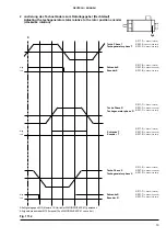
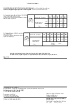
Page 24: ... EMF W U Signal earth measuring lead to U M15 Klemme15amUmrichter SIMODRIVE6SC61 M15 terminal 15 on SIMODRIVE 6SC61 converter Fig 111 1 0 Low High Low High Low High Schranke R Masse der Meßleitung an M15 Position encoder R Signalearth measuringleadtoM15 Schranke T Masse der Meßleitung an M15 Position encoder T Signalearth measuringleadtoM15 X 311 8 1 Achse 1st axis X 321 8 2 Achse 2nd axis X 331 8...

Page 25: ...e R Tachogenerator phase R Schranke R Encoder R 0 Low High Low High Low High Tacho Phase S Tachogenerator phase S X 311 2 1 Achse 1st axis X 321 2 2 Achse 2nd axis X 331 2 3 Achse 3rd axis X 311 9 1 Achse 1st axis X 321 9 2 Achse 2nd axis X 331 9 3 Achse 3rd axis X 311 1 1 Achse 1st axis X 321 1 2 Achse 2nd axis X 331 1 3 Achse 3rd axis X 311 8 1 Achse 1st axis X 321 8 2 Achse 2nd axis X 331 8 3 A...

Page 26: ...min max N m 1 1 1 6 3 5 5 3 17 25 8 5 12 5 M4 M5 M6 M8 M10 Bei Festigkeitsklassen 4 8 und 5 6 nach DIN ISO 898 sowiebeinichtrostendenWerkstoffen Applicable to strength classes4 8 and5 6 to DIN ISO 898andstainlessmaterials Bei Festigkeitsklassen 8 8 und 8 oder höher nach DIN ISO 898 Applicable to strength classes 8 8 and 8 or higher to DIN ISO 898 3 5 9 70 165 42 24 M4 M5 M6 M8 M10 M12 M16 Die obig...

Reviews: