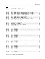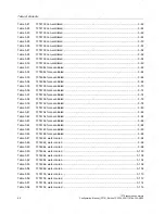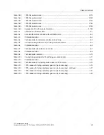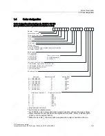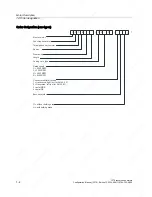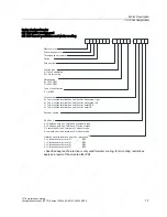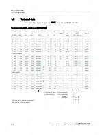
Table of Contents
Tables
Table 1
Configuration Manual, individual sections .................................................................................... iii
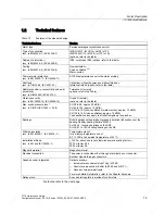
Table 1-1
Features of the standard design ................................................................................................ 1-3
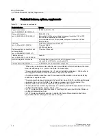
Table 1-2
Options and supplements .......................................................................................................... 1-4
Table 1-3
Resistor braking for the 1FT6 series, shaft heights 28 to 48, non-ventilated .......................... 1-15
Table 1-4
Resistor braking for the 1FT6 series, shaft heights 63 to 80, non-ventilated .......................... 1-16
Table 1-5
Resistor braking for the 1FT6 series, shaft heights 100 to 132, non-ventilated ...................... 1-17
Table 1-6
Resistor braking for the 1FT6 series, force-ventilated............................................................. 1-18
Table 1-7
Resistor braking for the 1FT6 series, water cooling ................................................................ 1-19
Table 1-8
Minimum clearance to parts and components mounted by the customer ............................... 1-22
Table 1-9
Technical data for the cooling circuit ....................................................................................... 1-23
Table 1-10
Materials used in the motor cooling circuit............................................................................... 1-24
Table 1-11
Manufacturers of chemical additives ....................................................................................... 1-25
Table 1-12
Cooling powers to be dissipated.............................................................................................. 1-26
Table 1-13
Assignment of the drive-out couplings to the motors............................................................... 1-28
Table 2-1
Description of the diagram......................................................................................................... 2-4
Table 2-2
Connections for the terminal box ............................................................................................... 2-4
Table 3-1
1FT6021 non-ventilated ............................................................................................................. 3-2
Table 3-2
1FT6024 non-ventilated ............................................................................................................. 3-4
Table 3-3
1FT6031 non-ventilated ............................................................................................................. 3-6
Table 3-4
1FT6034 non-ventilated ............................................................................................................. 3-8
Table 3-5
1FT6041 non-ventilated ........................................................................................................... 3-10
Table 3-6
1FT6044 non-ventilated ........................................................................................................... 3-12
Table 3-7
1FT6061 non-ventilated ........................................................................................................... 3-14
Table 3-8
1FT6061 non-ventilated ........................................................................................................... 3-16
Table 3-9
1FT6062 non-ventilated ........................................................................................................... 3-18
Table 3-10
1FT6062 non-ventilated ........................................................................................................... 3-20
Table 3-11
1FT6064 non-ventilated ........................................................................................................... 3-22
Table 3-12
1FT6064 non-ventilated ........................................................................................................... 3-24
Table 3-13
1FT6081 non-ventilated ........................................................................................................... 3-26
Table 3-14
1FT6081 non-ventilated ........................................................................................................... 3-28
Table 3-15
1FT6082 non-ventilated ........................................................................................................... 3-30
Table 3-16
1FT6082 non-ventilated ........................................................................................................... 3-32
Table 3-17
1FT6084 non-ventilated ........................................................................................................... 3-34
Table 3-18
1FT6084 non-ventilated ........................................................................................................... 3-36
Table 3-19
1FT6086 non-ventilated ........................................................................................................... 3-38
Table 3-20
1FT6086 non-ventilated ........................................................................................................... 3-40
1FT6 synchronous motors
Configuration Manual, (PFT6), Edition 12.2004, 6SN1197-0AD12-0BP0
xi
Summary of Contents for 1FT6031-4AK71-4AH0-Z
Page 3: ... VLQDPLFV RQILJXUDWLRQ 0DQXDO GLWLRQ 6 QFKURQRXV 6HUYRPRWRUV 7 ...
Page 4: ......
Page 8: ......
Page 266: ......
Page 267: ......


