Motor components
5.3 Holding brake (option)
1FT7 Synchronous Motors
210
Configuration Manual, (PFT7S) 01/2009, 6SN1197-0AD13-0BP2
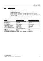
Table 5- 4
Example: Electronic components for the recommended circuit
Electr.
component
Examples
F
3RV10 circuit-breaker with current
paths connected in series (if
required with mounted auxiliary
contact 3RV1901 to provide a
feedback signal for the drive).
or
Miniature circuit-breaker 5SX21 (if
required with mounted auxiliary contact
to provide a feedback signal for the
drive).
K1
Auxiliary contactor 3RH11
or
Contactor 3RT10
R2
Varistor SIOVS14K30 (EPCOS)
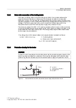
&XUUHQW,
W
,
9ROWDJH9
W
W
%UDNHRSHQHG
9
W RSHQLQJWLPH
W FORVLQJWLPH
PHDVXUHGDW9 9
F
F
Figure 5-3
Terminology (time) for holding operation
5.3.5
Technical data of the holding brake
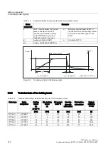
Table 5- 5
Technical data of the holding brakes used for 1FT7 Compact motors
Holding
torque
M
4
at 120° C
Min. braking
torque
M
1
DC current
at 20 °C
Opening
time with
with varistor
Closing time
with varistor
Highest
switching
energy
Motor type
Brake
designation
[Nm]
[Nm]
[A]
[ms]
[ms]
[J]
1FT703⃞
HT04P01
3
1,5
0,3
60
25
30
1FT704⃞
HT07P01
8
5
0,6
90
30
270
1FT706⃞
HT09P01
18
11
0,8
150
50
880
1FT708⃞
HT11P01
48
25
1,0
220
65
1900
1FT710⃞
HT14P01
85
35
1,6
250
70
5300
Summary of Contents for 1FT7 Series
Page 2: ......
Page 12: ...Preface 1FT7 Synchronous Motors 12 Configuration Manual PFT7S 01 2009 6SN1197 0AD13 0BP2 ...
Page 251: ......


