Maintenance
6.3 Corrective Maintenance
A5E01083943A AB
82
Siemens AG Operating Instructions 2.02 1FW4
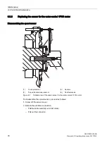
1.
Unscrew the fan cowl.
2.
Screw off the sensor cover.
3.
Detach the electrical connection.
–
Pull the cable carefully out of its holder.
–
Pull out the connector.
4.
Remove the torque counteracting support of the sensor.
5.
Pull the sensor off the shaft with the aid of a pressure screw.
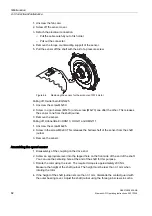
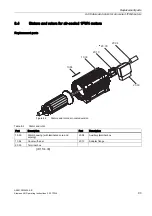
Figure 6-4
Replacing the sensor for the air-cooled 1FW4 motor
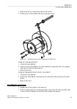
Pulling off, Heidenhain EQN 425:
1.
Unscrew the screw M5x50.
2.
Screw in a grub screw (M5x10) and a screw (M6x70) one after the other. This releases
the sensor cone from the shaft journal.
3.
Remove the sensor.
Pulling off, Hübner-Berlin HOG10, HOG11 and HMG111:
1.
Unscrew the screw M6x25.
2.
Screw in the screw M8x60. This releases the hollow shaft of the sensor from the shaft
journal.
3.
Remove the sensor.
Assembling the speed sensor
1.
Disassembly of the coupling on the drive end.
2.
Screw an appropriate lever into the tapped hole on the front side of the end of the shaft.
You can use the centering hole at the end of the shaft for this purpose.
3.
Rotate the rotor using the lever. The required torque is approximately 200 Nm.
Measure the height of the shaft journal. The height must be less than 0.1 mm when
rotating the rotor
4.
If the height of the shaft journal is more than 0.1 mm, dismantle the contact guard with
the outer bearing cover. Adjust the shaft journal using the three grub screws in such a
Summary of Contents for 1FW4
Page 1: ...Three phase synchronous motor HT direct Type 1FW4 Operating Instructions 01 2009 ht direct ...
Page 2: ...14 01 2009 16 26 ...
Page 24: ......
Page 40: ......
Page 60: ......
Page 88: ......
Page 92: ......
Page 102: ......
Page 108: ......
Page 113: ......
Page 114: ......
Page 115: ......
Page 116: ......

