background image

Description 


2.5 Layout 


A5E00215731A AD 

20


Siemens AG  Operating Instructions 2.02  1PL618 

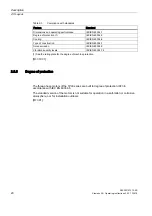
Table 2-3 

Compliance with standards 

Feature 

Standard 

Dimensions and operating performance 

IEC/EN 60034-1 

Degree of protection (1) 

IEC/EN 60034-5 

Cooling 

IEC/EN 60034-6 

Type of construction 

IEC/EN 60034-7 

Noise emission 

IEC/EN 60034-9 

Vibration severity levels 

IEC/EN 60034-14 

(1) See the rating plate for the degree of machine protection.  

[ID: 319.01] 

2.5.5


Degree of protection 


The three-phase motors of the 1PL6 series are built to degree of protection IP23 in 

accordance with IEC EN 60034-5. 
The standard version of the motors is not suitable for operation in a salt-laden or corrosive 

atmosphere, nor for installation outdoors. 
[ID: 391] 

Summary of Contents for 1PL618 Series

Page 1: ...Operating Instructions Edition 03 2008 Three phase induction motor AC COMPACT DRIVES Type 1PL618 ...

Page 2: ...18 03 2008 13 20 ...

Page 3: ...tion 1 Description 2 Transport assembly and connection 3 Start up 4 Operation 5 Faults 6 Maintenance 7 Spare parts 8 Notes 9 Three phase induction motor AC COMPACT DRIVES 1PL618 Operating Instructions Edition 03 2008 ...

Page 4: ...n Commissioning and operation of a device system may only be performed by qualified personnel Within the context of the safety notes in this documentation qualified persons are defined as persons who are authorized to commission ground and label devices systems and circuits in accordance with established safety practices and standards Prescribed Usage Note the following WARNING This device may onl...

Page 5: ...2 5 1 Cooling 17 2 5 2 Drive 18 2 5 3 Construction types 18 2 5 4 Regulations 19 2 5 5 Degree of protection 20 3 Transport assembly and connection 21 3 1 Transport storage and maintenance 21 3 1 1 Transport storage 21 3 1 2 Storage 22 3 1 3 Preservation 23 3 2 Assembly 24 3 2 1 Installation 24 3 2 2 Mounting 26 3 3 Electrical connection 27 3 3 1 Safety note for the drive CLIQ interface 27 3 3 2 Co...

Page 6: ...inspection 55 7 2 3 Main service 56 7 3 Corrective Maintenance 57 7 3 1 Instructions for repair 57 7 3 2 Dismantling 57 7 3 3 Re assembly 61 7 3 4 Screw type connections 62 7 3 5 Replacing the sensor module 63 8 Spare parts 65 8 1 Orders for spare parts 65 8 2 Spare parts 1PL6 66 9 Notes 69 Index 73 Tables Table 2 1 Technical support 15 Table 2 2 Motor rating plate technical specifications 16 Tabl...

Page 7: ...Figure 2 3 View from above onto construction type IM B3 19 Figure 3 1 1 Cover sheet detailed view 26 Figure 3 2 Connecting direction UVW for connection voltages of 400 V 480 V 28 Figure 3 3 Tightening torques for contact nuts and mounting bolts contact nut mounting bolt 30 Figure 3 4 Detailed view of fan for operation at 50 Hz 33 Figure 3 5 Fan for operation at 60 Hz 33 Figure 3 6 Detailed view Pl...

Page 8: ......

Page 9: ...onnel Commissioning and operation of this machine are to be carried out by qualified personnel only For the purpose of the safety information in this Instruction Manual a qualified person is someone who is authorized to energize ground and tag equipment systems and circuits in accordance with established safety procedures 1 2 Safety and application instructions The safe use of electrical machines ...

Page 10: ...tions relating to installation connection ambient and operating conditions are taken into account at all times The system specific installation and safety regulations are observed Personal protective equipment is used Work on or in the vicinity of these machines by unqualified persons is prohibited If the machines are used outside industrial areas the installation site must be safeguarded against ...

Page 11: ... s health or even death It is therefore forbidden for persons with heart pacemakers to enter these areas The plant operator is responsible for taking appropriate measures labels and hazard warnings to adequately protect operating personnel and others against any possible risk Observe the relevant nationally applicable health and safety regulations In Germany electromagnetic fields are subject to r...

Page 12: ...nded Electronic modules should not be brought into contact with electrically insulating materials such as plastic foil plastic parts insulating table supports or clothing made of synthetic fibers Always place electrostatic endangered assemblies on conductive bases Always store and transport electronic modules or components in conductive packaging e g metallized plastic or metal containers Note If ...

Page 13: ...nts A5E00215731A AD Siemens AG Operating Instructions 2 02 1PL618 11 1 Sitting 2 Standing 3 Standing sitting ESD protective measures a conductive floor b ESD table c ESD footwear d ESD coat e ESD wrist strap f cubicle ground connection ID 6006 01 ...

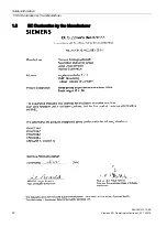
Page 14: ...Safety information 1 5 EC Declaration by the Manufacturer A5E00215731A AD 12 Siemens AG Operating Instructions 2 02 1PL618 1 5 EC Declaration by the Manufacturer ...

Page 15: ...Safety information 1 6 EC Declaration of Conformity A5E00215731A AD Siemens AG Operating Instructions 2 02 1PL618 13 1 6 EC Declaration of Conformity ...

Page 16: ......

Page 17: ...nter Contact for further information Details regarding the design of this electrical machine and the permissible operating conditions are described in these operating instructions If you have any questions or suggestions or if you require additional information please contact the Siemens Service Center Table 2 1 Technical support Phone 49 0 180 50 50 222 Europe Germany Fax 49 0 180 50 50 223 Ameri...

Page 18: ... to the appropriate SIEMENS office immediately These Operating Instructions are included in the scope of delivery and must be kept in a location where they can be easily accessed The rating plate enclosed as a loose item with the delivery ensures that the motor data can also be affixed on or near the machine or system ID 303 02 2 4 Rating plate The motor rating plate shows the technical specificat...

Page 19: ...ctor cos φ 15 Maximum speed rpm ID 307 02 2 5 Layout 2 5 1 Cooling Description The three phase motors of the 1PL6 series are externally and enclosed ventilated low voltage induction motors with a squirrel cage rotor and a separately driven fan unit mounted as standard The motors have an internal cooling circuit cooling method IC06 according to DIN EN IEC 60034 6 Cooling process basic type ཱ Figure...

Page 20: ... guarantee the necessary flow of cooling air Securing the cooling capacity CAUTION Missing cover sheets can result in considerably reduced cooling capacity and thus cause an inadmissible temperature rise within the motor Please ensure that the cover sheets are always mounted ID 973 00 2 5 2 Drive Description The variable speed three phase motors of the 1PL6 series are supplied with power by a freq...

Page 21: ... to 3000 rpm see also Planning Guide Note For additional instructions and restrictions for construction types that do not correspond to the basic type please refer to the Planning Guide Additional hoisting points for different construction types option Additional hoisting points are provided for those construction types that differ from the basic construction types IM B3 and IM B35 see Fig ແ ແ Fig...

Page 22: ...e of construction IEC EN 60034 7 Noise emission IEC EN 60034 9 Vibration severity levels IEC EN 60034 14 1 See the rating plate for the degree of machine protection ID 319 01 2 5 5 Degree of protection The three phase motors of the 1PL6 series are built to degree of protection IP23 in accordance with IEC EN 60034 5 The standard version of the motors is not suitable for operation in a salt laden or...

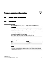
Page 23: ...lds Auxiliary eyebolts e g on fan cowls and cooler attachments are suitable only for hoisting the respective parts To hoist the motor in particular at attachments and built on assemblies use suitable cable guidance or spreading equipment Observe the lifting capacity of the hoisting gear For weight see rating plate and table Weights of standard versions Table 3 1 Weights of standard versions IM B3 ...

Page 24: ...ng notes on storage Storing outdoors Store the machine in a location that meets the following criteria Choose a dry storage location with plenty of space which is safe from flooding and free from vibrations Repair any damage to the packaging before putting the equipment into storage insofar as this is necessary to ensure proper storage conditions Position machines devices and crates on pallets woo...

Page 25: ...damage to bearings due to vibration On machines that have been supplied with a rotor locking device secure the rotor as per the notes on transportation Protect the machine against strong radial vibrations since the rotor locking device might not absorb these completely Condensation water Condensation water can collect in the machine as a result of sharp fluctuations in ambient temperature exposure...

Page 26: ...onents while the motor is running or immediately after it has been running CAUTION When positioning temperature sensitive components wires etc make sure that they are not in contact with the motor enclosure NOTICE Note also the technical specifications on the rating plates on the motor enclosure Cooling conditions in general In the case of motors that are cooled by the ambient air the cooling air ...

Page 27: ...ancing quality The rotors are balanced dynamically In the case of shaft ends with feather keys the method used to balance the rotors can be identified from the following coding to be found on the end face at the drive end of the shaft end Code H means balancing with half a feather key standard version this means that in order to maintain the balancing quality it may be necessary to cut back the pa...

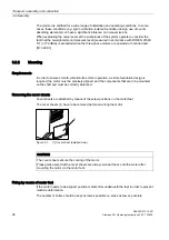
Page 28: ...g Requirements In order to ensure smooth vibration free motor operation a stable foundation design is required the motor must be precisely aligned and the components that are to be mounted on the shaft end must be correctly balanced Removing the cover sheets Cover sheets are attached by means of the screw positions on the motor feet The cover sheets 1 have to be removed before mounting the motor ແ...

Page 29: ...ted as a result of their type of construction to the wall using the motor feet must be fixed in place using an adequately dimensioned positive form fit e g using studs or mounting rails ID 331 02 3 3 Electrical connection 3 3 1 Safety note for the drive CLIQ interface CAUTION Electrostatically sensitive devices The drive CLIQ interface contains components that are susceptible to electrostatic char...

Page 30: ...ction of rotation resulting from the installation itself are not shown in the information on the rating plate and need to be considered separately when making the connections Terminal designations The following definitions apply in principle to the terminal designations of three phase motors in accordance with DIN VDE 0530 Part 8 or IEC 60034 8 Table 3 3 Terminal designations with the 1U1 1 as an ...

Page 31: ...2 2 x 50 191 1PL6186 F 1XB7 422 2 x M72 x 2 56 3 x M12 2 x 70 242 1PL6186 L 1XB7 700 3 x M72 x 2 56 3 x 2 x M12 3 x 150 583 8 th digit of the MLFB 7 8 1PL6 184 B 1PL6184 D 1PL6184 F 1XB7 322 2 x M50 x 1 5 38 3 x M12 2 x 50 191 1PL6184 L 1XB7 422 2 x M63 x 1 5 53 3 x M12 2 x 70 242 1PL6186 B 1PL6186 D 1XB7 322 2 x M50 x 1 5 38 3 x M12 2 x 50 191 1PL6186 F 1XB7 422 2 x M63 x 1 5 53 3 x M12 2 x 70 24...

Page 32: ...rands cannot be damaged Note We recommend you use shielded cables whose shields are conductively connected to a large area of the metal terminal box of the motor with an EMC cable gland made of metal NOTICE Unused threads must be sealed with a metallic screw plug Internal equipotential bonding The equipotential bonding between the ground terminal in the terminal box housing and the motor frame is ...

Page 33: ...specifications Then close the terminal box Table 3 5 Tightening torque for the fixing screws on the lid Bolt Terminal box type Tightening torque M6 1XB7 322 4 5 Nm M8 1XB7 422 11 Nm M10 1XB7 700 22 Nm ID 335 01 3 3 3 Connecting the ground conductor General The cross section of the ground conductor of the motor must comply with the regulations for electrical installations e g DIN EN IEC 60204 1 Wir...

Page 34: ...tor from being switched on when the fan unit is not in operation CAUTION Please note that the separately driven fan unit is only suitable for the direction of rotation shown by the direction of rotation arrow The fan must not be operated with the wrong direction of rotation as this could lead to the motor being destroyed Note The direction of rotation arrow and the direction of movement of the fan...

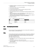
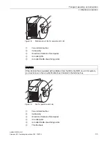
Page 35: ...n of fan impeller Air outlet grille Air outlet throttle sheet fixing points CAUTION If the standard fan is operated with ventilation from the DE to the NDE on a 60 Hz system you must screw on the air outlet throttle sheet included in the terminal box ཱི ཱུ ཱ ི ུ Figure 3 5 Fan for operation at 60 Hz Fan unit terminal box Cable entry Direction of rotation of fan impeller Air outlet grille Air outlet ...

Page 36: ...the speed sensor Connection Connect the speed sensor to the terminal box by means of a plug in connection It is located on top of the box housing Figure 3 6 Detailed view Plug in connection Note The plug in connection may differ from the standard layout in the case of special orders In the version without sensor an armored conduit union is located here ...

Page 37: ...gnal connection The signal connection between the motor and the converter is via the DRIVE CLiQ cable MOTION CONNECT Always use prefabricated cables from SIEMENS Thes cables reduce the mounting installation time and costs and increase operational reliability Push the connector on the DRIVE CLiQ cable into the socket until the catch spring latches into place Pay attention to the coding of the conne...

Page 38: ...3 8 Sensor Module mounted on terminal box NOTICE Changing the cable outlet direction by any improper means will cause damage to the connecting cables The permissible rotation range must not be exceeded A maximum of ten changes to the rotation angle of the Sensor Module are permissible within the rotation range ID 964 3 3 7 Connecting the temperature sensor Connection Connect the wires of the tempe...

Page 39: ...l connection A5E00215731A AD Siemens AG Operating Instructions 2 02 1PL618 37 Note The plug in connection may differ from the standard layout in the case of special orders In the version without sensor an armored conduit union is located here ID 342 ...

Page 40: ......

Page 41: ... WARNING Hazardous voltage During the measurement and immediately afterwards hazardous voltage levels are applied on some of the terminals and they should not be touched Touching live components can be result in death or serious injury Never touch the terminals when measuring or immediately after the measurement Check the supply feeder cables connected in order to ensure that the line supply volta...

Page 42: ...tion resistance is close to the minimum value then the cause could be humidity and or fouling Over its operating lifetime the motor winding insulation resistance can drop due to ambient and operational influences The critical insulation resistance at a winding temperature of 25 C is 2 5 MΩ NOTICE Critical insulation resistance is reached or insufficient If the critical insulation resistance is rea...

Page 43: ...the rating plate The power output elements have the proper setting conditions according to type for example Couplings are aligned and balanced The belt tension is properly adjusted if there is a belt drive Gear tooth flank play and gear tooth tip play as well as radial play are properly adjusted if there is gearwheel drive The minimum insulation resistance values are maintained The grounding and e...

Page 44: ...frequency converter have been assigned correctly We recommend you use appropriate commissioning tools e g Drive ES or STARTER CAUTION If the motor is not running smoothly or is emitting abnormal noises de energize it and determine the cause of the fault as the motor runs down NOTICE The critical speed nmax 5000 rpm is the maximum operating speed permissible over short periods ID 369 01 ...

Page 45: ...hus effective cooling of the motor Removing the covers during operation can result in death serious injury and property damage Never open covers during operation CAUTION Speed monitoring The motor is designed for a certain speed range If a motor is operated at impermissible speeds damage to the winding bearings or complete destruction of the motor can be the result Ensure that the speeds specified...

Page 46: ...in doubt switch off the drive in question immediately ID 348 See also Rating plate Page 16 Power on Page 42 5 2 Stoppages Measures when motors are at standstill and ready for operation For longer periods when the motor is not being used either energize the motor at regular intervals roughly once a month or at least spin the rotor Please refer to the section Energizing before restarting the motor N...

Page 47: ...ting Measures Always refer to the respective manual of the frequency converter when de energizing Note The fan must be shut down during longer periods in which the motor is not operated NOTICE We strongly recommend that you continue operating the fan for approx 30 min after shutting down the motor ID 351 ...

Page 48: ......

Page 49: ...wrong direction of rotation of fan Check air passages clean filter replace fan if necessary x Rotor not balanced Rebalance rotor x Rotor out of true shaft bent Consult the manufacturer x Poor alignment Align motor unit check coupling 2 x x Coupled motor not balanced Rebalance coupled motor x Shocks from coupled motor Check coupled motor x Imbalance originating from gearing Adjust repair gearing x ...

Page 50: ...ult characteristics Motor will not start up Motor starts up slowly Drumming noise during startup Drumming noise during operation Drumming noise in time with twice slip frequency High temperature rise at no load High temperature rise under load High temperature rise of individual winding sections Note If electrical faults occur please refer to the manual for the frequency converter ID 353 ...

Page 51: ...necessary specialist know how are entrusted to carry out work on power installations In addition to the main phases also ensure that supplementary and auxiliary circuits are also de energized CAUTION Be careful of those parts of the motor that get hot and let them cool down before starting maintenance work Safety regulations Always comply with the following safety rules before starting maintenance...

Page 52: ...e of the SIEMENS Service Centers to carry out the maintenance work for you ID 401 01 See also Siemens Service Center Page 15 7 1 2 Maintenance intervals General Careful and regular maintenance inspections and overhauls are essential for detecting and eliminating faults in good time before they can cause any damage Operating situations and characteristics can vary widely For this reason only genera...

Page 53: ...brational severity is 2 8 mm s measured on the end shield of the impeller side motor bearing Regularly clean and inspect the fan Impeller and frame are subject to natural wear depending on the area of application and displacement medium WARNING Impeller can crack Due to deposits and the resulting imbalance there is a hazard of fatigue fracture of the impeller The impeller can crack in operation De...

Page 54: ... relubrication intervals are stated on the lubrication instruction plate of the three phase motor NOTICE Observe the basic lubrication interval see section entitled Measures intervals NOTICE If there is a long interval between delivery and commissioning of the motor the bearings must be relubricated The grease change intervals apply for normal loads operation at speeds corresponding to those speci...

Page 55: ...ervals NOTICE Never mix greases that have different thickening agents and base oils Initial lubrication ESSO Unirex N grease is used for initial lubrication of the bearings prior to delivery Lubricating using the regreasing device ཱ Figure 7 1 D end and N end end shields with grease nipples Button head lubricating nipple to DIN 3404 size M10x1 drive end DE Button head lubricating nipple to DIN 340...

Page 56: ... outside each bearing in the used grease chamber of the outer bearing cap Remove the used grease when you replace a bearing NOTICE You have to separate the active parts of the bearings to replace the grease that is in the greasing channel Cleaning the cooling air passages Regularly clean the cooling air passages through which the ambient air flows e g using dry compressed air NOTICE The frequency ...

Page 57: ...e replaced ID 366 7 2 2 Initial inspection Inspection interval for initial inspection The initial inspection once the three phase motor is assembled and commissioned is under normal circumstances conducted after approx 500 operating hours but at the latest after 6 months Conducting the initial inspection While the motor is running check that the equipment conforms to the stated electrical characte...

Page 58: ...ating years Conducting the major inspection While the motor is running check that the equipment conforms to the stated electrical characteristics the smooth running characteristics and motor noise during operation have not deteriorated When the motor has been shut down check that the motor foundation has no indentations or cracks the motor is aligned within the permissible tolerance ranges all of ...

Page 59: ...rial damage can result if the required covers are removed or if the device is not operated properly Before starting work on the motor and in particular before opening the covers of live parts make sure that the motor or system is properly isolated WARNING Proper transport Only transport the motor in accordance with the transport guidelines Death serious injury or material damage can be the result ...

Page 60: ...aching the rotor in the vertical position make sure that the centering recesses in the shaft ends DIN 332 DS M20 have a recessed thread eye bolts must have a minimum length of 35 mm The rotor weights for the 1PL6 three phase motors can be found in the following table 1PL618 Size 184 186 Weight kg 100 120 Disassembling the three phase motor To disassemble the motor disconnect the connecting cables ...

Page 61: ...antling and assembling the bearings make sure that you match up the components correctly bearings preloading springs equalizing rings caps with different centering length etc especially when the bearings at the drive end and non drive end are the same size NOTICE Label the components before dismantling NOTICE Whenever you work on the locating bearing when the three phase motor is in its vertical p...

Page 62: ... as follows 1 Screw off the sensor cover 2 Detach the electrical connection Pull the cable carefully out of its holder Pull out the connector 3 Remove the screw connections holding the sensor on the end shield 4 Pull the sensor off the shaft with the aid of a puller There are two ways of doing this 0 0 0 ແ ໂ Figure 7 3 Disassembling the speed sensor forcing off 1st option Unscrew the screw M5x50 S...

Page 63: ... a straightening plate This ensures that the feet surfaces are all on the same level NOTICE When mounting the end shield make sure that the windings that project from the stator housing do not become damaged NOTICE Take great care and pay attention to cleanliness when fitting and assembling the bearings Sealing measures when reassembling Clean bare joints between parts before reassembling e g betw...

Page 64: ...st also be installed without a spring ID 378 01 7 3 4 Screw type connections Tightening torque for screwed union connections The screwed union connections with metal contact surfaces end shields active bearing parts terminal box parts bolted onto the stator frame should be tightened to the following torque with a tolerance of 10 depending on the thread size Table 7 3 Tightening torque for screwed ...

Page 65: ... Sensor Module contains motor specific and sensor specific data and an electronic nameplate If you operate a different Sensor Module on the motor this can result in serious injury or death or cause considerable material damage Only operate the sensor module on the original motor Do not install the sensor module on other motors Do not replace the sensor module with a sensor module from a different ...

Page 66: ......

Page 67: ...number is also stamped on the end face of the shaft end on the drive end Serial number of the motor Example End shield drive end part 5 00 See rating plate for motor type and serial number Commercially available standard components can be used but ensure that they have the same construction type dimensions strength class etc When replacing rolling contact bearings in addition to the bearing identi...

Page 68: ...Spare parts 8 2 Spare parts 1PL6 A5E00215731A AD 66 Siemens AG Operating Instructions 2 02 1PL618 8 2 Spare parts 1PL6 Spare parts Figure 8 1 Spare parts 1PL6 ...

Page 69: ...etaining ring 4 40 Deep groove ball bearing locating bearing 4 50 Inner bearing cap 5 00 End shield DE 6 00 End shield NDE 6 44 Cover 6 80 Sensor cover 8 00 Rotor complete 10 00 Stator housing with laminated core and winding 10 53 Hoisting lug 13 80 Grease nipple Terminal box 20 20 Terminal box with terminal support 20 30 Lid terminal box 20 50 Entry plate terminal box 32 12 Fan unit complete 55 1...

Page 70: ......

Page 71: ..._______________ ________________________________________________________________________________ ________________________________________________________________________________ ________________________________________________________________________________ ________________________________________________________________________________ ____________________________________________________________...

Page 72: ...______________ ________________________________________________________________________________ ________________________________________________________________________________ ________________________________________________________________________________ ________________________________________________________________________________ _____________________________________________________________...

Page 73: ..._______________________________________________________ ________________________________________________________________________________ ________________________________________________________________________________ ________________________________________________________________________________ ________________________________________________________________________________ ____________________...

Page 74: ......

Page 75: ...e 22 C Condensation water 23 D Degree of protection 20 E External fan Maintenance 51 I Initial inspection 55 Inspection interval 55 P Preservation 23 R Rating plate 16 S Sensor module 27 63 Siemens Service Center 15 Storage 22 Storage location 22 T Tightening torque Screwed union connections 62 ...

Page 76: ......

Page 77: ......

Page 78: ......

Page 79: ...AB U151 Herstellererklärung AB U161 Konformitätserklärung ...

Page 80: ......

Reviews: