UM353-1B
Installation
April 2012
7-15
7.4.5 Thermocouple Input Wiring
Function blocks AINU1 and AINU2 can be configured for thermocouple or RTD input.
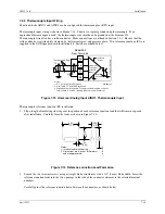
Thermocouple input wiring is shown in Figure 7-13. Shown is a typical grounded tip thermocouple. If an
ungrounded thermocouple is used, the thermocouple wire shield can be grounded at the Siemens 353.
Thermocouple wire often has a solid conductor. Make connections as outlined in Section 7.4.1. Be sure that the
solid conductor is satisfactorily clamped by the terminal screw and pressure plate. Two reference junctions (RJ) are
supplied in the I/O Expander board installation kit. Install as outlined below.
T/C
RJ
45
46
47
48
_
+
C
ontr
o
lle
r C
ir
c
ui
tr
y
Notes:
1. RJ - Cold Junction Reference
2. See Table 7-1 for AINU2 terminals.
3. Grounded junction shown. For ungrounded junction, connect
cable shield to AINUc_ (Analog Input Universal Common).
Isolated
Power
Isolated
Ground
Universal
Converter,
Isolated
Inputs
+
_
MG00512a
Thermocouple Wire
Model 353
Rear Terminals
Figure 7-13 Universal Analog Input AINU1, Thermocouple Input
Thermocouple reference junction (RJ) installation:
1.
Slip a length of insulating sleeving over the portion of each reference junction lead that will remain exposed
after installation. Carefully form the leads as shown in Figure 7-14.
0.63
(15.9)
0.3
(7.9)
0.06
(1.5)
0.1
(0.25)
Notes:
1. Insulate leads with sleeving.
2. Dimensions are in inches (millimeters)
and are approximate.
M
G
0039
0a
0.5
(12.7)
Figure 7-14 Reference Junction Lead Formation
2.
Loosen the two terminal screws using a straight blade screwdriver with a 1/8
″
(3 mm) blade width. Insert the
reference junction leads into the two openings in the side of the connector adjacent to the selected terminal
numbers.
Carefully press the reference junction down between the connectors, as shown below.
Summary of Contents for 353
Page 12: ...Contents UM353 1B x April 2012 ...
Page 22: ...Introduction UM353 1B April 2012 1 10 ...
Page 30: ...Configuration Overview UM353 1B April 2012 2 8 ...
Page 122: ...Function Blocks UM353 1B April 2012 3 92 ...
Page 168: ...Data Mapping UM353 1B April 2012 6 28 ...
Page 204: ...Controller and System Test UM353 1B April 2012 9 8 ...
Page 222: ...Calibration UM353 1B April 2012 11 4 ...
Page 226: ...Circuit Description UM353 1B April 2012 12 4 ...
Page 238: ...Model Designation and Specifications UM353 1B April 2012 13 12 EC Declaration of Conformity ...
Page 240: ...Model Designation and Specifications UM353 1B April 2012 13 14 ...
Page 244: ...Abbreviations And Acronyms UM353 1B 14 4 April 2012 ...


