UM353-1B
Maintenance
April 2012
10-11
10.5.2.2 To Replace the Bezel or Circuit Board
REMOVAL
1.
Place a properly grounded wrist strap on your wrist and remove the Display Assembly as described
above.
2.
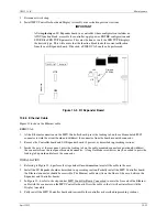
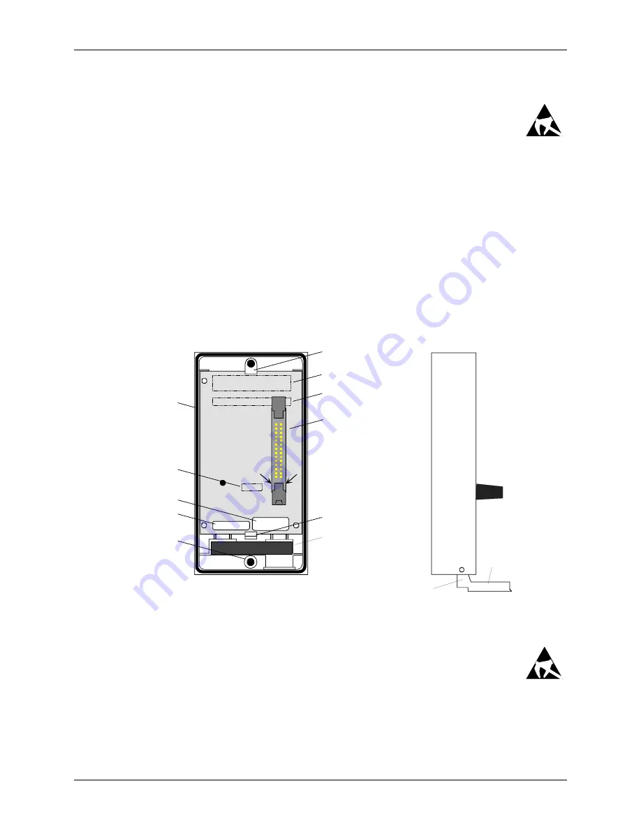
Refer to Figure 10-4. Notice that the circuit board is captured by a Fixed Retainer at the top of the
bezel and a Flexible Retainer at the bottom. Grasp the body of the connector at (1) and at the same time press
the Flexible Retainer downward slightly. Pull gently on the connector to lift the bottom edge of the board above
the Flexible Retainer.
Note
The board is a snug fit. Do not squeeze the bezel sides and make removal more difficult.
3.
Remove the board from the bezel by carefully continuing to lift board while pulling the board out from under to
Fixed Retainer at the top of the assembly.
4.
If the bezel is being replaced:
1)
Remove the two Display Assembly mounting screws. Turn the Assembly face up and lift each mounting
screw upward until the threaded portion contacts the bezel. Turn each screw counterclockwise to unscrew
it from the bezel. A screwdriver may be needed once a screw is started.
2)
Remove the flip-down door by pressing on the door near its pivot point to free the door from the bezel.
Fixed Board Retainer
Numeric Display (2)
Alphanumeric Display (2)
Connector
Flexible Board Retainer
O-Ring Gasket
Keypad
Connector (2)
Part Number
Mounting Screw,
2 Places
Serial Number
(1)
(1)
Notes:
(1) - Grasp at this point
when removing board.
(2) - On other side of
board.
(3) - Press to remove and
install door.
MG
0038
7a
Foam
(3)
Flip-Down
Door
Rear View
Side
View
Figure 10-4 Display Assembly Repair
INSTALLATION
1.
Place an anti-static wrist strap on your wrist and connect the ground lead.
2.
Get the replacement bezel, or get the replacement circuit board and remove it from the anti-static
bag.
3.
If the bezel is being replaced, start threading each Faceplate mounting screw into the bezel. Use a screwdriver
to complete screw installation. Install the flip-down door; see Figure 10-4.
4.
Turn the bezel over.
Summary of Contents for 353
Page 12: ...Contents UM353 1B x April 2012 ...
Page 22: ...Introduction UM353 1B April 2012 1 10 ...
Page 30: ...Configuration Overview UM353 1B April 2012 2 8 ...
Page 122: ...Function Blocks UM353 1B April 2012 3 92 ...
Page 168: ...Data Mapping UM353 1B April 2012 6 28 ...
Page 204: ...Controller and System Test UM353 1B April 2012 9 8 ...
Page 222: ...Calibration UM353 1B April 2012 11 4 ...
Page 226: ...Circuit Description UM353 1B April 2012 12 4 ...
Page 238: ...Model Designation and Specifications UM353 1B April 2012 13 12 EC Declaration of Conformity ...
Page 240: ...Model Designation and Specifications UM353 1B April 2012 13 14 ...
Page 244: ...Abbreviations And Acronyms UM353 1B 14 4 April 2012 ...


