UM353-1B
Configuration Overview
April 2012
2-5
•
At the STATION level, a factory configured option can be loaded, station parameters can be configured,
security passwords can be entered, the clock can be set, communication parameters can be configured, and
inputs and outputs can be calibrated.
•
Calibration can also be performed within individual loops containing the input or output function blocks used in
the LOOP.
•
At the LOOP level, new loops can be added, loops can be deleted, or an existing loop can be edited.
When a new loop is created at the controller faceplate, the controller will assign a default name (e.g. LOOP01). The
default loop name can be changed to a new name that is up to 12 ASCII characters in length. It is suggested that
loop names be limited to 6-characters so that the complete loop name will appear in the alphanumeric display during
normal operation.
A loop can be edited by stepping down from the EDIT menu. If more than one loop has been configured, press the
STEP DOWN button and turn the Pulser Knob to step through the list of configured loops. From the selected loop,
stepping down will provide various options within the specific loop.
•
The current value of all configured block outputs can be viewed.
•
The current tag name of the loop and the ESN (Execution Sequence Number) can be changed. ESNs are
automatically assigned by the controller in the order of creation, either a loop or individual block. An ESN
should be changed when it is important that one loop be executed prior to another (e.g. cascade primary
executes prior to the cascade secondary).
•
Function blocks can be added to or deleted from the loop. Existing function blocks can be edited. Use the step
up and step down buttons to move between the function block, parameter, and value levels within the EDIT FB
menu.
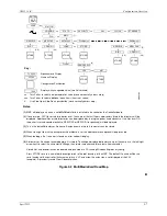
Once all configuration entries have been made and stored, press EXIT CONIF to exit the configuration mode. The
configuration will be written to the root directory of the MultiMediaCard with a file name that is the serial number
of the controller. Each time the configuration is edited and the EXIT CONF button pressed, the configuration is
again written to the root directory of the card overwriting the stored file. The current version of the configuration is
always stored on the MMC. If an archive copy of a particular configuration version is desired, create a new file and
save it with a new file name; refer to Figure 2-2, Note 6 to create a new file name.
If no configuration entries are made for about three minutes, the mode will time out and the controller will exit the
configuration mode. The STATN function block has a CONFG TO (Configuration Timeout) parameter to enable or
disable timeout.
2.6 OPERATION DURING LOCAL ON-LINE CONFIGURATION
Changing a controller’s configuration parameters while the station is on-line can affect its operation and output
values. Configuration parameters are divided into four types: HARD, SOFT, READ, and CALIBRATION.
HARD - When a HARD parameter is STORED the controller will suspend execution of all function blocks and will
hold all outputs until the EXIT button is pressed. A HARD parameter is identified with each ‘(H)’ notation in a
function block parameter listing in Section 3 Function Blocks. When a loop or function block is added or deleted,
the station enters a HARD configuration mode.
SOFT - A SOFT function block parameter can be changed while the function blocks are executing. A SOFT
parameter is identified with each ‘(S)’ notation in a function block parameter listing in Section 3. All QUICKSET
changes also fall into this category.
READ - These parameters are not changeable and therefore can be read while the station function blocks are
executing. A READ parameter is identified with each ‘(R)’ notation in a function block parameter listing in Section
3. The configuration VIEW mode also falls into this category.
Summary of Contents for 353
Page 12: ...Contents UM353 1B x April 2012 ...
Page 22: ...Introduction UM353 1B April 2012 1 10 ...
Page 30: ...Configuration Overview UM353 1B April 2012 2 8 ...
Page 122: ...Function Blocks UM353 1B April 2012 3 92 ...
Page 168: ...Data Mapping UM353 1B April 2012 6 28 ...
Page 204: ...Controller and System Test UM353 1B April 2012 9 8 ...
Page 222: ...Calibration UM353 1B April 2012 11 4 ...
Page 226: ...Circuit Description UM353 1B April 2012 12 4 ...
Page 238: ...Model Designation and Specifications UM353 1B April 2012 13 12 EC Declaration of Conformity ...
Page 240: ...Model Designation and Specifications UM353 1B April 2012 13 14 ...
Page 244: ...Abbreviations And Acronyms UM353 1B 14 4 April 2012 ...

