47
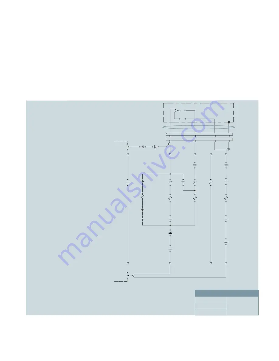
Figure 16: Typical ground and test device schematic
Legend:
l
88 - Spring charging motor
l
52SRC - Spring release coil (close)
l
52T - Shunt trip coil (trip)
l
52Y - Closing relay (anti-pump)
l
LS3 - Spring-charge switch (open when
spring is charged)
l
LS5, LS6 - Blocks electrical operation
between TEST and CONNECT positions
l
LS9 - Spring-charge switch (closed when
spring is charged)
l
LS21, LS22 - Spring-charge position switch
(cutoff motor after spring charge)
l
SD - Secondary disconnect
l
R - Twist lock receptacle
l
AS/52a - Auxiliary switch (open when
ground and test device is open)
l
AS/52b - Auxiliary switch (closed when
ground and test device is open)
l
TS/C - Selector switch (close)
(non-spring return)
l
TS/T - Selector switch (trip)
(non-spring return)
l
PB/C - Pushbutton (close)
l
PB/T - Pushbutton (trip).
Schematic shown with:
l
Closing springs discharged
l
Ground and test device open
l
Ground and test device located in
DISCONNECT, TEST or CONNECT position.
Pushbutton enclosure
4/C cable
White
Red
Black
Green
Receptacle plug
Ground and test device mounted receptacle
W R
X R
Y R
G R
34
33
16
17
(+)
52a
TS
T
(-)
125 Vdc
supply
PB/
C
PB/
T
TC
D2 XO
D7 XO
D7
TC1
TC2
A1
52T
A2
T3
23
24
52a
T2
12
13
TS
T
C2 XO
T1
T
31
32
52b
C7 XO
C7
B2 XO
B7 XO
6
6
SD
15
11
18
A2 XO
C1
C
TS
C
21
22
LS3
C2
C3
A1
52Y
A2
14
13
52Y
41
42
52b
21
22
LS21
PW1
Blue
C4
A1
52SRC
A2
88
Motor
Green
22
21
LS22
43
44
52Y
CC5
13
14
LS9
CC3
CC2
A1 XO
PW
51
52
52b
14
15
TS
C
CC1
CC
B7
13
14
LS41
A7
A7 XO
5
SD
16
22 21
LS5 5A
22 21
LS6
Coils
Supply
Motor
>125 Vdc
Close
Trip
Schematic


