background image


Product features 


5.8 Operating motor starters 

Motor starter (3RK1308‑0**00‑0CP0)


Equipment Manual, 11/2019, A5E34821005002A/RS-AC/003 

55


Variant 2. High Feature DOL starter or reversing starter with 230 V brake 
The current for the braking device is drawn from only one switched phase. Connection is via 

T1. 
The single-phase connection of the motor brake leads to phase asymmetry at the motor 

connection. This is detected by the motor starter, which responds based on its parameter 

settings and the magnitude of the asymmetry. 
Asymmetry limit: 
The asymmetry limit is a percentage value by which the motor current is allowed to deviate 

in each phase. Asymmetry is detected as soon as one of the three phases deviates by more 

than 40 % from the mean value of all phases. 
Response to asymmetry: 
You use this device parameter to determine the behavior of the motor starter in the event of 

asymmetry: 


Warning (not permissible for fail-safe motor starters in ATEX operation) 


Shutdown 


Note 
Using brake motors 
When using brake motors, you have to increase the set rated motor current by the braking 

current (see example on motor and brake starting current later in this chapter). 


NOTICE 
Using this mode 
This operating mode is not suitable for 3RK1308-0C and 3RK1308-0D fail-safe  

motor starters as there is a connection to the neutral conductor. 


Summary of Contents for 3RK1308-0 00-0CP0 Series

Page 1: ...Motor starter 3RK1308 0 00 0CP0 ...

Page 2: ......

Page 3: ...002A RS AC 003 Introduction Security information 1 Information about third party software 2 Product specific safety instructions 3 Documentation guide 4 Product features 5 Functions 6 Parameters address space 7 Alarms diagnostic messages 8 Technical data 9 CAx data 10 Data sets A Circuit examples B ...

Page 4: ... be operated only by personnel qualified for the specific task in accordance with the relevant documentation in particular its warning notices and safety instructions Qualified personnel are those who based on their training and experience are capable of identifying risks and avoiding potential hazards when working with these products systems Proper use of Siemens products Note the following WARNI...

Page 5: ...on on installation connection and the installation conditions of the ET 200SP motor starter The information provided in this Equipment Manual the System Manual and the function manuals enables you to commission the ET 200SP distributed I O system Basic knowledge required A general knowledge of the following areas is needed in order to understand this manual Industrial controls Digital circuit logi...

Page 6: ...machine not designed by Siemens Nor can Siemens assume liability for recommendations that appear or are implied in the following description No new guarantee warranty or liability claims beyond the scope of the SIEMENS general terms of supply are to be derived or inferred from the following description Siemens Industry Online Support Information and service At Siemens Industry Online Support you c...

Page 7: ...roving authority type and country Characteristics For support in planning and configuring your system Product announcements The latest information and news concerning our products Downloads Here you will find updates service packs HSPs and much more for your product Application examples Function blocks background and system descriptions performance statements demonstration systems and application ...

Page 8: ...cialist in Technical Support My notifications Make sure you always have the latest information individually tailored to your needs My filters Simple management and re use of your filter settings from Product Support and the Technical Forum My favorites Create your own knowledge database by assigning Favorites and Tags to documents simply and efficiently Entries last viewed Clear presentation of yo...

Page 9: ...llowing links Link for Android Link for iOS Link for Windows Phone Support Request Using the Support Request form in Online Support you can send your query directly to our Technical Assistance After describing your query in a few guided steps you will immediately be provided with possible suggestions for solving the problem Support Request Internet https support industry siemens com My ww en reque...

Page 10: ...Introduction Motor starter 3RK1308 0 00 0CP0 10 Equipment Manual 11 2019 A5E34821005002A RS AC 003 ...

Page 11: ... Electromagnetic compatibility 39 5 3 Designing motor starters in conjunction with electromechanical switching devices 41 5 4 Applications 43 5 5 Permissible ambient temperatures up to 1000 m above sea level 44 5 6 Permissible ambient temperatures at more than 1000 m above sea level 46 5 7 Device versions 47 5 8 Operating motor starters 48 6 Functions 63 6 1 Overview of functions 63 6 2 Intrinsic ...

Page 12: ... 6 8 3 Ex motor application 101 6 9 Response to CPU master STOP 102 6 10 Group fault diagnostics group warning diagnostics 103 6 11 Inputs 104 6 12 Manual local local control 111 6 13 Trip without restart 112 6 14 Trip with restart 113 6 15 Trip emergency end position CW 114 6 16 Trip emergency end position CCW 116 6 17 Group warning 117 6 18 Emergency start 118 6 19 Motor CW 119 6 20 Motor CCW 12...

Page 13: ... 158 8 Alarms diagnostic messages 161 8 1 Status and error displays 161 8 2 TEST RESET button 167 8 3 Interrupts 168 8 4 Maintenance 170 9 Technical data 171 9 1 Technical data in Siemens Industry Online Support 171 9 2 Final conditions for safety related parameters 172 10 CAx data 173 10 1 CAx data 173 A Data sets 175 A 1 Reading and writing of data records 175 A 2 Byte arrangements 176 A 3 DS68 ...

Page 14: ...6 4 I M 2 Read write installation 203 A 16 5 I M 3 Read write description 203 B Circuit examples 205 B 1 Connection examples for motor starters 205 B 1 1 Connecting and operating motor brakes 205 B 1 2 Example of the correct engineering of a motor starter 205 B 1 3 Induction machine 206 B 1 4 Single phase motor 207 B 1 5 Resistive load 208 B 1 6 Gas discharge lamps 209 B 2 Connection examples for ...

Page 15: ...ts should only be connected to an enterprise network or the internet if and to the extent such a connection is necessary and only when appropriate security measures e g firewalls and or network segmentation are in place For additional information on industrial security measures that may be implemented please visit https www siemens com industrialsecurity Siemens products and solutions undergo cont...

Page 16: ...Security information Motor starter 3RK1308 0 00 0CP0 16 Equipment Manual 11 2019 A5E34821005002A RS AC 003 ...

Page 17: ... LGPL Licensed Module whereas the LGPL Licensed Module and the components that the LGPL Licensed Module is combined with or linked to is the Combined Product the following additional rights apply if the relevant LGPL license criteria are met i you are entitled to modify the Combined Product for your own use including but not limited to the right to modify the Combined Product to relink modified ve...

Page 18: ...t SIEMENS does not make any warranty commitment on behalf of or binding upon any third party licensor Open Source Software and or other third party software contained in this Product If you like to receive a copy of the source code please contact SIEMENS at the following address Siemens AG LC TE SL Werner von Siemens Str 60 91052 Erlangen Germany Subject Open Source Request please specify Product ...

Page 19: ...THIS SOFTWARE IS PROVIDED BY THE COPYRIGHT HOLDERS AND CONTRIBUTORS AS IS AND ANY EXPRESS OR IMPLIED WARRANTIES INCLUDING BUT NOT LIMITED TO THE IMPLIED WARRANTIES OF MERCHANTABILITY AND FITNESS FOR A PARTICULAR PURPOSE ARE DISCLAIMED IN NO EVENT SHALL THE COPYRIGHT OWNER OR CONTRIBUTORS BE LIABLE FOR ANY DIRECT INDIRECT INCIDENTAL SPECIAL EXEMPLARY OR CONSEQUENTIAL DAMAGES INCLUDING BUT NOT LIMIT...

Page 20: ...Information about third party software Motor starter 3RK1308 0 00 0CP0 20 Equipment Manual 11 2019 A5E34821005002A RS AC 003 ...

Page 21: ...static charge The motor starter can become damaged by an electrostatic charge if the unoccupied pins of the motor starter are contacted When handling and installing the ET 200SP motor starter ensure protection against electrostatic charging of the components Changes to the system configuration and wiring are only permissible after disconnection from the power supply It is only permitted to connect...

Page 22: ...A5E34821005002A RS AC 003 3 2 Safety information for hazardous areas WARNING Explosion hazard in Class I and Class II Hazardous Locations Can cause death or serious injury The fail safe motor starter is permitted for the operation of device group II Cat 2 area G D The fail safe motor starter itself must not be located in the hazardous area ...

Page 23: ... barriers around them WARNING Hazardous Voltage Work on live parts of the ET 200SP motor starter system can result in death or serious injury The device is only allowed to be commissioned and operated by qualified personnel For the purpose of the safety information in this documentation a qualified person is someone who is authorized to energize ground and tag equipment systems and circuits in acc...

Page 24: ...amage is also possible To ensure the safety function in the case of a single phase load route the phase and the neutral conductor through the motor starter You will find additional information next to the connection examples in chapter Single phase motor Page 207 In the case of a three phase load do not connect the neutral conductor to the star point of the load NOTICE Electromagnetic interference...

Page 25: ...described in the catalog and in the technical description and only in conjunction with non Siemens equipment and components recommended by Siemens Correct transport storage installation and assembly as well as careful operation and maintenance are required to ensure that the product operates safely and without faults EU note Commissioning is absolutely prohibited until it has been ensured that the...

Page 26: ...rements on the part of the operator The supplier is also obliged to comply with special product monitoring measures For this reason we publish a special newsletter containing information on product developments and features that are or could be relevant to operation of safety related systems By subscribing to the appropriate newsletter you will ensure that you are always up to date and able to mak...

Page 27: ...es stated including amendments and that the stated standards were applied in their design and construction You can download the entire EC Declaration of Conformity Declaration of Conformity http www siemens com sirius approvals Standards The table below shows the standards that each of the ET 200SP motor starters comply with Standard Direct on line starter Reversing starter Fail safe direct on lin...

Page 28: ...Product specific safety instructions 3 6 Declaration of conformity Motor starter 3RK1308 0 00 0CP0 28 Equipment Manual 11 2019 A5E34821005002A RS AC 003 ...

Page 29: ...ic content you require Basic information The System Manual and Getting Started describe in detail the configuration installation wiring and commissioning of the SIMATIC ET 200SP distributed I O system The STEP 7 online help supports you in the configuration and programming Device information Product manuals contain a compact description of the module specific information such as properties wiring ...

Page 30: ...e Internet http support automation siemens com WW view en 84133942 mySupport With mySupport your personal workspace you make the best out of your Industry Online Support In mySupport you can save filters favorites and tags request CAx data and compile your personal library in the Documentation area In addition your data is already filled out in support requests and you can get an overview of your ...

Page 31: ...on examples support you with various tools and examples for solving your automation tasks Solutions are shown in interplay with multiple components in the system separated from the focus on individual products You will find the application examples on the Internet https support industry siemens com sc ww en sc 2054 TIA Selection Tool With the TIA Selection Tool you can select configure and order d...

Page 32: ...verted to UTC time to the module Program download to CPU RUN STOP mode switchover CPU localization by means of LED flashing Reading out of CPU error information Reading of the CPU diagnostics buffer Reset to factory settings Firmware update of the CPU and connected modules You can find the SIMATIC Automation Tool on the Internet https support industry siemens com cs ww en view 98161300 PRONETA SIE...

Page 33: ...ssioning or failures during productive operation even in advance of a planned operation This increases the availability of the production plant and helps improve operational safety The advantages at a glance Network optimization thanks to port specific calculation of the network load Increased production availability thanks to online scan and verification of existing systems Transparency before co...

Page 34: ...Documentation guide Motor starter 3RK1308 0 00 0CP0 34 Equipment Manual 11 2019 A5E34821005002A RS AC 003 ...

Page 35: ...08 0BA00 0CP0 RS 0 3 1 A HF 3RK1308 0BB00 0CP0 RS 0 9 3 A HF 3RK1308 0BC00 0CP0 RS 2 8 9 A HF 3RK1308 0BD00 0CP0 RS 4 0 12 A HF including fan 3RW4928 8VB00 3RK1308 0BE00 0CP0 Fail safe direct on line starters F DS 0 1 0 4 A HF 3RK1308 0CA00 0CP0 F DS 0 3 1 A HF 3RK1308 0CB00 0CP0 F DS 0 9 3 A HF 3RK1308 0CC00 0CP0 F DS 2 8 9 A HF 3RK1308 0CD00 0CP0 F DS 4 0 12 A HF including fan 3RW4928 8VB00 3RK1...

Page 36: ...ct device with hybrid technology The ET 200SP motor starter has electronic overload protection for switching of three phase asynchronous motors and single phase AC motors up to 5 5 kW at 500 V during normal operating conditions Fail safe variants of the motor starter are also available The figure below shows an ET 200SP HF motor starter Figure 5 1 View of the ET 200SP motor starter with mounted 3D...

Page 37: ...roperties Switching and protection device for three phase asynchronous motors and single phase AC motors Integrated short circuit and overload protection Direct on line or reversing start function Fail safe motor starters additionally support safety related disconnection Safe Torque Off The fail safe variants of the motor starter are therefore suitable for the following uses Safety related applica...

Page 38: ...strips in various versions 500 units light gray on a roll 6ES7193 6LR10 0AA0 500 units yellow on a roll 6ES7193 6LR10 0AA0 1000 units light gray on DIN A4 sheets 6ES7193 6LA10 0AG0 1000 units yellow on DIN A4 sheets 6ES7193 6LA10 0AG0 160 reference identification labels 6ES7193 6LF30 0AW0 3DI LC module 3RK1908 1AA00 0BP0 Fan 3RW4928 8VB00 is already included with all 4 12 A motor starters Mechanic...

Page 39: ...the ET 200SP station with an unused BaseUnit a cover must be provided for the open BaseUnit plug contacts power connector power bus connector and backplane bus connector The cover protects the plug contacts against dirt The BU cover can be ordered as an accessory Note Use of interference suppressors with hybrid switchgear No EMC protective wiring e g RC element or varistor interference suppression...

Page 40: ...nce immunity Interface module Motor starter Digital input module Motor starter Digital output module Server module Dummy module Infeed bus cover Motor starter NOTICE Ensuring interference immunity You must not plug any other module into the BaseUnit of the dummy module otherwise interference immunity is no longer ensured Note Using a dummy module The dummy module cannot be configured in all versio...

Page 41: ... motors with an output of 1 kW with correspondingly high inductance e g with a contactor can cause an inductive voltage of several 1000 V with steep voltage edges depending on the switching time This can also occur multiple times due to the bouncing of the contactor contacts and the resultant arcs For a contactor this leads to increased contact erosion wear and to high electromagnetic load on othe...

Page 42: ...sed service life of the contactor because it always switches without load Use of RC elements on the 3 motor phases As a consequence the voltage peaks and also the steep voltage rise are reduced Figure 5 3 Use of RC elements for reducing voltage peaks The following RC elements are suitable 3RK1911 6EA00 for direct attachment to the motor terminal board 3RK1911 6EB00 for direct attachment to the mot...

Page 43: ...0SP motor starters wherever you want to switch and protect drives up to 5 5 kW with an ET 200SP system The ET 200SP motor starters are used for the following for example Conveyor technology Logistics systems Production machines Machine tools Gas discharge lamps Fail safe motor starters are designed exclusively for the switching and protection of motor loads ...

Page 44: ... the standard mounting rail The following maximum permissible ambient temperatures apply depending on the mounting position Horizontal mounting position 60 C Vertical mounting position 50 C Observe the following general conditions when using the motor starters Parameterized rated operational current Ie Current of the infeed system 500 V AC Current of the power bus 24 V DC Fan operation the fan swi...

Page 45: ...0 C 1 25 55 C 1 20 50 C 1 9 A Up to max 50 C 1 2 Up to max 50 C 1 2 Up to max 50 C 1 2 Up to max 50 C 1 2 10 A Up to max 45 C 1 2 Up to max 45 C1 2 Up to max 45 C 1 2 Up to max 45 C 1 2 1 In operation with power bus up to 32 A the maximum usage temperature is reduced by 10 K 2 Fans are included in the scope of supply 2 Operation with power bus 24 V DC in accordance with UL CSA requirements NOTICE ...

Page 46: ...on 1000 m 100 see above 2000 m 92 60 C 50 C 3000 m 85 54 C 45 C 4000 m 78 48 C 40 C The Ie values can be interpolated on the basis of the available altitude specifications NOTICE Derating of the nominal rated data for the insulation coordination beyond specific altitudes above sea level Up to an elevation of 2000 m above sea level operation is possible without derating of the nominal rated data fo...

Page 47: ...or currents to the motor powers are recommended values Due to the introduction of energy efficient motors IE3 IE4 to the market rated currents are falling for any given power At the same time the start up currents rise NOTICE Dimensioning instructions Take the current characteristics of the connected motor and motor starter into account when dimensioning The following characteristic values are rel...

Page 48: ...on of the ET 200SP motor starters with the TIA Portal software SIMATIC STEP 7 V13 or higher is possible with a GSD file GSDML Checking switching elements The switching elements semiconductors relays are checked automatically when the motor is switched off and on via the motor starter The switching elements cannot be checked in the following operating states During operation Motor ON In the switche...

Page 49: ...nt detected Residual current disconnection This message can be acknowledged by the Trip Reset Reset pushbutton If the supply voltage is interrupted during switching on or off this may lead to a device fault entry 308 in data set 92 Page 186 In addition the following entries in DS72 logbook Read device error Page 180 are possible 20017 Residual current detection during switching on off routine or b...

Page 50: ...pter Electromagnetic compatibility in ET 200SP System Manual https support industry siemens com cs ww de view 58649293 en dl en WARNING Safety related shutdown via the F DI Depending on peripherals used the shutdown takes place via one or two output channels terminals PM switching The shutdown takes place via two output channels PP switching The shutdown takes place via one output channel Shutdown...

Page 51: ... on the permissible read back time Increase the power supply unit s output voltage to minimize the risk of incorrect deactivation during dark tests By trial and error set the read back time as low as possible but so high that the output channel is not deactivated WARNING Inadvertent starting of the motor if the bright test lasts too long The motor can start if the bright test lasts more than 10 ms...

Page 52: ...General information on the dimensioning of SITOP power supplies when ET 200SP motor starters are used can be found in Industry Online Support under FAQ ET 200SP motor starter https support industry siemens com cs ww en ps 21800 faq Peak current in the electric torque Number of motor starters Current in A Time in ms until 8 A rated current is reached 1 25 0 145 2 47 0 24 3 64 0 32 4 78 0 36 5 91 0 ...

Page 53: ...ke Variant 3 High Feature DOL starter or reversing starter and F DOL starter or F reversing starter with 230 V brake without connection to the neutral conductor Variant 1 High Feature DOL starter or reversing starter and F DOL starter or F reversing starter with 400 V brake The current for the braking device is drawn from two phases Connection is via T1 and T3 The connection of the motor brake lea...

Page 54: ... the behavior of the motor starter in the event of asymmetry Warning not permissible for fail safe motor starters in ATEX operation Shutdown Note Using brake motors When using brake motors you have to increase the set rated motor current by the braking current see example on motor and brake starting current later in this chapter Figure 5 5 Connection of a 400 V brake to an ET 200SP motor starter ...

Page 55: ...a percentage value by which the motor current is allowed to deviate in each phase Asymmetry is detected as soon as one of the three phases deviates by more than 40 from the mean value of all phases Response to asymmetry You use this device parameter to determine the behavior of the motor starter in the event of asymmetry Warning not permissible for fail safe motor starters in ATEX operation Shutdo...

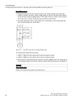
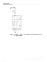
Page 56: ...8 Operating motor starters Motor starter 3RK1308 0 00 0CP0 56 Equipment Manual 11 2019 A5E34821005002A RS AC 003 Figure 5 6 Connection of a 230 V brake with connection to the neutral conductor to an ET 200SP motor starter ...

Page 57: ...responds based on its parameter settings and the magnitude of the asymmetry Asymmetry limit The asymmetry limit is a percentage value by which the motor current is allowed to deviate in each phase Asymmetry is detected as soon as one of the three phases deviates by more than 40 from the mean value of all phases Response to asymmetry You use this device parameter to determine the behavior of the mo...

Page 58: ...ting motor starters Motor starter 3RK1308 0 00 0CP0 58 Equipment Manual 11 2019 A5E34821005002A RS AC 003 Figure 5 7 Connection of a 230 V brake in star connection and connection to the neutral point on an ET 200SP motor starter ...

Page 59: ...ng starter High Feature F DOL starter High Feature F reversing starter NOTICE Brake properties The brake properties vary depending on the type of connection Please observe the information provided by the motor manufacturer Note 1 The brake closing time is influenced accordingly by the type of connection and the selected braking device For detailed information see the documentation provided by the ...

Page 60: ...ted ISt Irated 2 45 A 8 19 6 A Maximum brake inrush current IB 8 0 5 A 8 4 A Motor starting current brake inrush current 19 6 A 4 A 23 6 A Maximum current carrying capacity of 3 A motor starter 3RK1308 0AC00 0CP0 30 A see also data sheet https support industry siemens com cs ww en ps 21800 faq https support industry siemens com cs ww en ps 21800 faq Result The maximum current carrying capacity is ...

Page 61: ...motors that are located in hazardous gas vapor mist and air mixtures and also combustible dust WARNING The motor starter is not suitable for installation in hazardous areas Due to the increased danger in hazardous areas observe the following standards EN 60079 14 VDE 0165 1 Explosive atmospheres Part 14 Electrical installations EN 60079 17 Explosive atmospheres Part 17 Electrical installations ins...

Page 62: ...Product features 5 8 Operating motor starters Motor starter 3RK1308 0 00 0CP0 62 Equipment Manual 11 2019 A5E34821005002A RS AC 003 ...

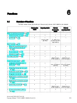
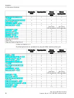
Page 63: ...g technology hybrid switching technology Page 70 x x x x Control function Page 73 x x Operating modes Page 74 x x x x Overload protection Page 76 x x x Restrictions in ATEX operation x Restrictions in ATEX operation Substation monitoring Page 88 Response to residual current detection Page 89 x x Only Deactivate possible Only Deactivate possible Upper lower current warning limit Page 93 x x x x Upp...

Page 64: ...x x x x Diagnosis Supply voltage too low x x x x 1 From FW Version 1 2 0 The following functions are available when using the 3DI LC module via the inputs Direct on line starter Reversing starter Fail safe direct on line starter Fail safe reversing starter Inputs Page 104 x x x x Manual local local control Page 111 x x x x Trip without restart Page 112 x x x x Trip with restart Page 113 x x x x Tr...

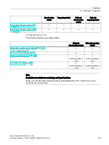
Page 65: ...2 0 The following functions are safety related Fail safe direct on line starter Fail safe reversing starter Response to safety related tripping Page 100 STO Safe Torque Off x x Ex motor application Page 101 x x Rated operational current Page 67 x ATEX application only x ATEX application only Overload protection Page 76 x ATEX application only x ATEX application only Note Restrictions in relation t...

Page 66: ... is output in DS92 Read device diagnostics Page 186 The entry Number of switching element overload trips in DS95 Read statistics Page 192 is incremented by 1 As of device firmware V1 2 0 the value of the device protection model can be read out via the DS94 Read measured values Page 191 If the intrinsic device protection was active the device s diagnostics function indicates a device fault NOTICE D...

Page 67: ...nt that the feeder can carry without interruption Usually the rated operational current of the motor is specified on the rating plate of the motor The adjustment range depends on the performance class of the ET 200SP motor starter Note Rated operational current The rated operational current is one of the key parameters You cannot disable motor protection completely However you can prevent the shut...

Page 68: ... 4 2 5 1 0 5 0 25 0 125 0 0625 0 03125 Sum 1 96875 0 0 0 0 0 0 Icurr 0 1 0 0 0 0 0 Icurr Irated x 1 1 0 1 1 0 0 Icurr Irated x 1 375 1 1 1 1 1 1 Icurr Irated x 1 96875 Icurr rated operational current Irated x value DI 1 0 to DI 1 5 Irated rated current of the motor Default setting In the ET 200SP motor starter the rated operational current is preset at the factory to the maximum value In the event...

Page 69: ...1 phase 3 phase operation In 3 phase operation you can operate a 3 phase asynchronous motor at the connections of the motor starter To ensure motor protection do not connect more than one motor to one motor starter Do not operate several single phase motors on one motor starter in three phase operation 1 phase operation In 1 phase operation you can operate a 1 phase asynchronous motor at the conne...

Page 70: ... the feeder you must ensure disconnection from the power e g by the position Parking position OFF You will find further information on the Parking position OFF in the System Manual This combination is known as hybrid switching technology Hybrid switching technology in the ET 200SP motor starter is characterized by the following properties Switching on The inrush current in the case of motorized lo...

Page 71: ... starter direct on line starter version Figure 6 1 Schematic circuit diagram of HF direct on line starter Figure 6 2 Schematic circuit diagram of fail safe direct on line starter The ET 200SP motor starters do not possess any galvanic isolation of the switching elements in the main circuits The isolating function in compliance with EN 60947 1 is only warranted in the parking position See also ET 2...

Page 72: ...ent 0 1 0 4 A 0 3 1 A 0 9 3 A 2 8 9 A 4 12 A Motor ohmic load of motor starter 0 05 0 15 0 18 0 56 0 8 Motor load of fail safe motor starter 0 05 0 15 0 45 1 4 2 As soon as the minimum current limit is undershot during operation the fault detection residual current detection picks up Disconnection or a warning is triggered depending on the setting of the Response to residual current detection para...

Page 73: ...restarting and changing direction of rotation are identical The execution times t0 until a device internal control command is active are different depending on the source of the control command 3DI LC module 10 ms debounce time t0 10 ms PIQ The times are dependent on the cycle clock of the field bus and the station topology 5 ms jitter ON commands within the interlock time are delayed ON commands ...

Page 74: ...matically when communication with the interface module or the higher level CPU is established Operating mode Manual bus Controlling the motor starter by means of software e g TIA Portal V16 via fieldbus is possible 1 Operating mode Manual local via the 3DI LC module highest priority The motor starter can be controlled as follows Set the Local Control LC on the 3DI LC module input to activate manua...

Page 75: ...Functions 6 4 Motor control Motor starter 3RK1308 0 00 0CP0 Equipment Manual 11 2019 A5E34821005002A RS AC 003 75 Figure 6 4 Operating modes 1 possible as of firmware version 1 2 0 ...

Page 76: ...been disconnected from the 24 V power supply the thermal motor model is at the same motor temperature rise state when the power supply is restored as it was before disconnection This behavior protects the motor against overload in the case of brief failures of the 24 V power supply With this setting you can therefore specify that the motor starter retains the thermal motor model when the power sup...

Page 77: ...g cooling time if the relevant parameters have been set When the control supply voltage is restored the remaining cooling time elapses before the load can be switched on again If you initiate a restart within a very short time after switching off the motor it may be that the motor memory model has not yet fully discharged This can result in an extremely fast overload trip after the restart In cont...

Page 78: ...Hazardous Voltage Can Cause Death Serious Injury or Property Damage When the cooling time has expired following an overload trip and a RESET takes place or automatic restart has been parameterized the machine starts up immediately if a control command is active People in the danger area may be injured Make sure that the danger area of the machine is kept clear of people Warning a general warning i...

Page 79: ... to IEC 60947 2 The tripping characteristics represent the time to trip as a function of the current multiple The continuous black line in the following diagrams illustrates the tripping characteristic curve for three pole symmetrical loads and for single phase loads The continuous red line illustrates the tripping characteristic curve for three pole loads when one phase fails The following diagra...

Page 80: ...6 5 Overload protection Motor starter 3RK1308 0 00 0CP0 80 Equipment Manual 11 2019 A5E34821005002A RS AC 003 The following diagram shows the overload protection for CLASS 5 Figure 6 7 CLASS 5 overload protection ...

Page 81: ...P0 Equipment Manual 11 2019 A5E34821005002A RS AC 003 81 The following diagram shows the overload protection for CLASS 10 Figure 6 8 CLASS 10 overload protection You can find out how to calculate the switching cycles in chapter Calculating switching cycles Page 83 ...

Page 82: ... elements in the main circuit against impermissible operating states an integrated intrinsic device protection is provided in the upper load range At overload currents greater than 65 A shutdown becomes effective earlier than with the motor protection function intrinsic device protection model The setting range of the overload protection is 1 3 You can find more information about intrinsic device ...

Page 83: ...itching frequency per hour of the 3RK1308 motor starter for the switch on duration of 0 5 s Current setting A 0 4 1 3 9 10 12 x starting current factor IStartup Ie Startup time s Number of starting operations per h 2 5 0 1 4131 4131 4131 4131 4131 4131 2 5 0 3 1377 1377 1377 1377 1377 1377 2 5 0 5 826 826 826 826 826 826 2 5 0 7 590 590 590 590 590 590 2 5 2 207 207 207 207 207 207 4 0 1 1446 1446...

Page 84: ...Functions 6 6 Calculating switching cycles Motor starter 3RK1308 0 00 0CP0 84 Equipment Manual 11 2019 A5E34821005002A RS AC 003 ...

Page 85: ... The maximum is the permissible current of the relevant device class Consider additional idle times in the case of starting currents in excess of 65 A see example graphics Also see Overload protection Page 76 and the example graphics Motor operation time tMotor s Time in which the motor is in operation after startup Rated operational current Ie A Root mean square of the motor current in the operat...

Page 86: ...nt of 65 A in the case of the 9 A and 12 A motor starters consider the device protection model for calculation of the switching cycles The following graphics show the minimum idle time depending on the starting current Minimum idle time TOff 9 A motor starter at IStartup Irated_motor 8 Minimum idle time TOff 12 A motor starter at IStartup Irated_motor 8 ...

Page 87: ... A5E34821005002A RS AC 003 87 Example for the minimum idle time TOff 12 A motor starter at IStartup Irated 8 The graphic below shows the minimum idle time of a 12 A motor starter with the following parameters Irated_motor 10 4 A Istartup Irated_motor 8 6 thus IStartup 89 A TStartup 0 125 s TOff 19 s ...

Page 88: ...ates more sluggishly e g due to bearing damage Current is higher than normal Upper current limit Upper current warning limit Motor operates more smoothly e g because the system has run out of processing material Current is lower than normal Lower current limit Lower current warning limit Motor is blocked Very high current flowing Blocking protection Open circuit Defective fuse Motor idling Power f...

Page 89: ...in the case of fail safe motor starters Tripping Note When the motor is switched on residual current detection is suppressed for approximately 1 s Residual current detection for motor starters with 0 1 0 4 A The following graphic shows the dependence of residual current detection on the set motor current in the case of motor starters with 0 1 to 0 4 A Figure 6 9 Residual current detection 0 1 0 4 ...

Page 90: ...l current detection 0 9 3 A device Residual current detection for motor starters with 2 8 9 A The following graphic shows the dependence of residual current detection on the set motor current in the case of motor starters with 2 8 to 9 A Figure 6 12 Residual current detection 2 8 9 A device Residual current detection for motor starters with 4 12 A The following graphic shows the dependence of resi...

Page 91: ...rent detection 0 1 0 4 A device Residual current detection for fail safe motor starters with 0 3 1 A The following graphic shows the dependence of residual current detection on the set motor current in the case of motor starters with 0 3 to 1 A Figure 6 15 Residual current detection 0 3 1 A device Residual current detection for fail safe motor starters with 0 9 3 A The following graphic shows the ...

Page 92: ...ce of residual current detection on the set motor current in the case of motor starters with 2 8 to 9 A Figure 6 17 Residual current detection 2 8 9 A device Residual current detection in the case of fail safe motor starters with 4 12 A The following graphic shows the dependence of residual current detection on the set motor current in the case of motor starters with 4 to 12 A Figure 6 18 Residual...

Page 93: ...dged as soon as the warning threshold is exceeded or undershot by 5 Note The current warning thresholds are activated by default You can deactivate the current warning thresholds however The current warning thresholds are not activated until the CLASS time expires Setting ranges The table below shows the possible setting range for the lower and upper current warning limits Device parameters Defaul...

Page 94: ...t values are deactivated An entry in the logbook data set 73 Page 182 is generated Example The following example shows an application for the upper and lower current limit The viscosity of the mixed mass is too high that is the upper current limit has been overshot No load because drive belt is broken In other words the lower current limit has been violated Note The parameterized current warning t...

Page 95: ...is set to Enabled a corresponding diagnostic interrupt is set if blocking protection responds Setting ranges The table below shows the possible setting range for the blocking current and the blocking time Device parameters Default setting Setting range Blocking current 800 150 1500 of Ie Increment 50 Blocking time 1 s 1 7 5 s Increment 0 5 s 6 7 5 Device protection model To protect the switching e...

Page 96: ... Motor starter 3RK1308 0 00 0CP0 96 Equipment Manual 11 2019 A5E34821005002A RS AC 003 The motor starter operates within a permissible current range The following graphic shows the permissible current range Figure 6 19 Device protection ...

Page 97: ...again Violation of the permissible current range Switching elements may be damaged if the permissible current range represented by the vertical line in the graphic is exceeded The motor starter switches off The Current measuring range overshot message is issued 9 A and 12 A motor starters switch off without the support of the semiconductors This is referred to as hard switching and is output as a ...

Page 98: ...tion The thermal device protection model can also lead to the activation of the fan 6 7 7 Asymmetry monitoring Description Three phase asynchronous motors respond to slight asymmetries in the supply voltage with a higher asymmetric current consumption As a result the temperature in the stator and rotor windings of the drive increases The ET 200SP motor starter protects the load against overload by...

Page 99: ... between two phases Switching performance The ET 200SP motor starter switches off short circuits in the motor or in the cables The ET 200SP motor starter complies with the requirements of type of coordination 1 IEC 60947 4 2 On tested assemblies the type of coordination defines the permissible condition of devices following a short circuit Type of coordination 1 means that the load feeder is non o...

Page 100: ...n 5 4 The drive is safely free from torque This state is monitored in the motor starter Safety related tripping is achieved for the fail safe motor starters thanks to the special arrangement and checking of the switching elements Safety related tripping is performed by a low level 0 signal at the F DI As an alternative safety related tripping can be achieved by removing the 24 V supply voltage fro...

Page 101: ...ot possible with the motor starter when it is used in 1 phase operation An ATEX approval is possible by means of further measures such as thermoclick Note It is not possible to set the motor protection to Class OFF in EX operation Settings Table 6 6 Settings for Ex motor application Device parameters Default setting Setting range Ex motor application No No Yes The maintenance alarm 0x1036 New safe...

Page 102: ...esponse of the PIQ following a CPU STOP Retain last value The last received and valid value of the process image of the outputs is retained Switch substitute value 0 The process image of the outputs is assigned the value 0 Switch substitute value 0 is active even if the header module of the ET 200SP station is deenergized Note The response to CPU master STOP is only relevant in Automatic mode ...

Page 103: ...tics parameter to Disable no diagnostic messages are output to the CPU If you set the group warning diagnostics parameter to Disable no maintenance alarms are output You will find the requirements for the use of maintenance alarms in an Maintenance FAQ https support industry siemens com cs ww en view 109485777 Settings Table 6 7 Settings for group fault group warning diagnostics Device parameter D...

Page 104: ...on of the input This input is always implemented as a NO contact You can detect whether or not manual local is active if bits 0 7 and 1 6 are active in the process image input For information on this topic see Chapter Connecting the 3DI LC module for the motor starter in the ET 200SP System Manual https support industry siemens com cs ww de view 58649293 en dl en Inputs for commissioning To ensure...

Page 105: ...s fixed at 10 ms Input n signal You can use this device parameter to determine whether or not the input level of the inputs is to be saved Retentive i e latching mode edge evaluation Regardless of the input signal present the action can only be deactivated again by a further event and remains active even after cancellation until it is overwritten by another action e g process image of the outputs ...

Page 106: ...to the input delay Note Applied input voltage If input voltage is applied input active the value 1 is transferred to the controller regardless of the Input n level parameter Input n action Different actions can be triggered when an input signal is present You can parameterize the following actions dependent on Input n level Input n signal and Mode Note If Input n signal retentive and Input n actio...

Page 107: ...en rectified initial status Trip end position CW NO NC n ret All The motor is switched off regardless of the direction of rotation A fault is generated and reported The motor can only be switched on with Motor CCW Trip end position CCW NO NC n ret All The motor is switched off regardless of the direction of rotation A fault is generated and reported The motor can only be switched on with Motor CW ...

Page 108: ... priority over Motor CW and Motor CCW Quick Stop clockwise NO NC n ret ret All Motor is switched off with Motor CW without group fault Quick Stop takes priority over Motor CW Quick Stop counter clockwise NO NC n ret ret All Motor is switched off with Motor CCW without group fault Quick Stop takes priority over Motor CCW The action is only available for reversing starters Trip RESET NO n ret All Tr...

Page 109: ... NC n ret All The motor is tripped regardless of the direction of rotation CW or CCW The motor can only be switched on with Motor CW The parameter can only be implemented as non retentive A group fault is not generated but a diagnostic message is set in data set 92 NO NO contact NC NC contact ret Retentive n ret non retentive activation and deactivation of the input action follows the status of th...

Page 110: ...level Input 1 action Motor CW No action Trip without restart Trip with restart Trip end position CW Trip end position CCW Group warning Emergency start Motor CW Motor CCW Quick Stop direction independent Quick Stop clockwise Quick Stop counter clockwise Trip RESET Cold start Operational trip end position CW Operational trip end position CCW Input 2 action Motor CCW RS No action DS Input 3 action C...

Page 111: ...the DI module That is with active input action Motor CCW or Motor CW the ET 200SP motor starter remains in manual local mode and thus in the Motor ON state as long as the input action is not interrupted Note Removal during operation If the 3DI LC module is removed from the ET 200SP motor starter during manual local mode this results immediately in shutdown of the running motor and then to exiting ...

Page 112: ...without restart The action Trip without restart results in the following behavior The motor is tripped Acknowledge disconnection via Trip Reset after remedying the cause of tripping You can then switch on the motor again The parameter can only be implemented as non retentive A group fault is generated and a diagnostics entry created ...

Page 113: ...03 113 6 14 Trip with restart The action Trip with restart results in the following behavior The motor is tripped Acknowledged automatically after the cause of the trip has been rectified input status The parameter can only be implemented as non retentive A group fault is generated and a diagnostics entry created ...

Page 114: ...l command Motor CW is issued in the case of trip end position CW DI static 1 an incoming diagnostic message trip end position CW is triggered only if the diagnostic message was already outgoing or has been deleted This diagnostic message prevents renewed switch on of the motor in the CW direction of rotation emergency start deactivated The action Trip end position CW results in the following behav...

Page 115: ...l Motor CW The group fault is deleted when the signal Motor CW is canceled You switch the motor on by means of Motor CW The motor is switched off by setting the digital input 1 parameterized to input action 1 Trip end position CW A group fault is generated at the same time by the starter While digital input 1 is set you can only run the motor counter clockwise The group fault is deleted when the s...

Page 116: ...rol command Motor CCW is issued in the case of trip limit CCW DI static 1 an incoming diagnostic message trip end position CCW is triggered only if the diagnostic message was already outgoing or has been deleted This diagnostic message prevents renewed switch on of the motor in the CCW direction of rotation emergency start deactivated The action Trip end position CCW results in the following behav...

Page 117: ...oup warning results in the following behavior A group warning is generated An entry with the object number 304 byte 0 bit 7 is generated in the DS92 Read device diagnostics Page 186 A logbook entry is created in the DS75 logbook Read events Page 184 The motor is not tripped A maintenance alarm is generated when group warning diagnostics is enabled ...

Page 118: ...n the following situations When you are using a fail safe motor starter in ATEX operation If a device fault is active If there is no switched unswitched 24 V DC supply voltage or if the supply voltage is outside the specified range The blocking protection has responded If a process image error is active You can activate the function Emergency start as follows PIQ 0 4 Emergency start Via the 3DI LC...

Page 119: ...tor via the 3DI LC module activate the LC input on the 3DI LC module manual local mode Bit 0 0 Motor CW in the process image of the outputs is ignored in manual local mode The parameter can only be implemented as an NO contact If Input n signal retentive and Input n action Motor CW CCW at least one input must always be parameterized with the Tripping or Quick Stop input action If this rule is viol...

Page 120: ...otor via the 3DI LC module activate the LC input on the 3DI LC module manual local mode Bit 0 1 Motor CCW in the process image of the outputs is ignored in manual local mode The parameter can only be implemented as an NO contact If Input n signal retentive and Input n action Motor CW CCW at least one input must always be parameterized with the Tripping or Quick Stop input action If this rule is vi...

Page 121: ...ggered The motor is switched on by Motor CW Motor is switched on by Motor CW then switched off by the rising edge at digital input 1 parameterized to input action 1 Quick Stop By revoking the Motor CW command the Quick Stop function is reset Motor is switched on by Motor CW then switched off by the rising edge at digital input 1 By setting Disable quick stop the Quick Stop function is reset and th...

Page 122: ...p function is reset by Disable quick stop The motor is switched on again since Motor CW is still active The motor is switched off by the level at digital input 1 The Quick Stop function is reset by setting Disable quick stop As the level Motor CW is still active the motor runs CW again until the Disable quick stop command is revoked Motor is switched on by Motor CW then switched off by the level a...

Page 123: ...e motor is not switched off with pending signal Motor CCW Quick Stop CW takes priority over Motor CW The input action responds to the active edge of the input signal which means deactivation is possible when the static input signal Quick Stop is present The input trigger is reset through cancelation of the control commands Motor CW or Disable quick stop in the process image This applies only in th...

Page 124: ...tor CW Quick Stop CCW takes priority over Motor CCW The input action responds to the active edge of the input signal Deactivation is possible when the static input signal Quick Stop is present The input trigger is reset through cancelation of the commands Motor CCW or Disable quick stop in the process image This applies only in the case of control via manual local mode or in the case of a retentiv...

Page 125: ...ledged if its cause has been rectified or if it is no longer present Trip RESET is triggered by Loading a valid parameterization Remote RESET via PLC PIQ bit 0 3 Trip RESET Remote RESET via input actions if parameterized TEST RESET button on the ET 200SP motor starter Power on reset switching off and on again of the 24 V supply voltages on the device Note TRIP RESET as input n signal The Trip Rese...

Page 126: ...e motor starter responds here as if the main power supply were connected to the system The error message Residual current detection tripping is suppressed Thus in the commissioning phase for example the relevant control commands are accepted from the controller and the relevant messages are sent Note The cold start function is not possible for the command Motor on in an ATEX configuration Note If ...

Page 127: ...or control command Motor CW is issued in the case of operational trip end position CW DI static 1 an operational trip is triggered again This motor tripping triggered by the operational trip end position prevents renewed switch on of the motor in the CW direction of rotation The action Operational trip end position CW results in the following behavior The motor is tripped regardless of the directi...

Page 128: ...r control command Motor CCW is issued in the case of operational trip end position CW DI static 1 an operational trip is triggered again This motor tripping triggered by the operational trip end position prevents renewed switch on of the motor in the CCW direction of rotation The action Operational trip end position CCW results in the following behavior The motor is tripped regardless of the direc...

Page 129: ...s of the relevant messages in the relevant data sets The last 21 entries are stored in the logbooks You can read out the entries with the relevant data sets The logbook is designed as a circular buffer After 21 entries the oldest entry is overwritten The latest entry is at the first location Logbook Read device errors The logbook Read device errors contains all device errors faults The object numb...

Page 130: ...g function and Measured value function for the motor current These are identified as commands since they trigger reactions in the ET 200SP motor starter In addition the ET 200SP motor starter also provides so called services that provide information on the status of the motor starter as defined in PROFIenergy These can then be evaluated and further processed in the user program Using PROFIenergy w...

Page 131: ...ded status of the current mode Query_Modes List_Energy_Saving_Modes Provides a list of supported energy saving modes Get_Mode Provides the parameter values with which the energy saving function works Query_Version Shows the implemented PROFIenergy profile Query_Measurement Get_Measurement_List Provides a list of supported measured values Get_Measurement_List_with_object_number Provides a list of s...

Page 132: ...mode Measured value function command Measured values for energy need to be supplied for efficient energy management The PROFIenergy specification offers various measured values from which to choose each of which is assigned a measured value ID The ET 200SP motor starter supports the instantaneous values of the phase current and the mean value of the phase currents as measured values The measured v...

Page 133: ...ta transmission PIQ PII data sets diagnostics alarms etc to and from the motor starter are still possible Prerequisites for the starter to switch to energy saving mode min idle time etc The changeover to Pause energy saving mode only becomes effective when the idle time sent is greater than the device specific minimum idle time This means that a switch is only performed when the pause is longer th...

Page 134: ... Support under the entry Firmware update for ET 200SP motor starter https support industry siemens com cs ww en view 109486088 Loading and installing a firmware update Click Product Support on the Siemens Industry Online Support https support industry siemens com page In the product tree selection field select Automation engineering Automation systems SIMATIC industrial automation systems Controll...

Page 135: ...dule on a rack Make sure before a firmware downgrade of fail safe motor starters with a F DI BaseUnit MS5 MS10 that the associated F DI is on 1 signal value of 1 Also make sure that the motor starter is only connected to the device on which the firmware is being updated e g PG PC or CPU NOTICE Loss of the safety function after an incorrect firmware update The safety functions can be lost if you in...

Page 136: ...starter state After completion of the update the current PIO and the input actions take effect again Unexpected operation of a process or a machine can lead to fatal or severe injuries and or to property damage Before installing the firmware update ensure that the motor starter the CPU and the interface module are not executing an active process More options for the firmware update The following o...

Page 137: ... to remove and insert the module before starting the firmware update again Procedure using a SIMATIC memory card Proceed as follows to perform a firmware update via the SIMATIC memory card 1 Insert a SIMATIC memory card into the SD card reader of your programming device computer 2 To save the update file on the SIMATIC memory card mark the SIMATIC memory card in the project navigator under Card re...

Page 138: ... type and the cooling time The sensor supply of the DI module remains active Behavior after the firmware update After the firmware update check the firmware version of the updated module A successfully loaded firmware update is activated immediately If a fail safe motor starter is in Manual local mode during the firmware update the motor starter switches to Commissioning mode Page 141 after the su...

Page 139: ... O system support the full parameterization scope of the ET 200SP motor starters Note List of supported ET 200SP header modules You will find a list of the compatible ET 200SP header modules in the Siemens Industry Online Support https support industry siemens com cs ww en view 109485777 Note Reduction to default parameters In the following cases the full scope of parameterization is reduced by th...

Page 140: ...sign parameters in the user program transfer the parameters to the module via the data sets with the WRREC statement The parameters that can be set can be found in the Appendix in Read write DS201 device parameter 1 Page 193 and Read write DS202 device parameter 2 Page 196 You will find an explanation of the parameters in Chapter Declaration of parameters Page 146 Note Changing the parameters duri...

Page 141: ... after confirmation via the TEST RESET button To switch to commissioning mode in the case of fail safe motor starters confirm the change with the blue button During ATEX operation additionally confirm the current parameters as described in chapter Configuring ATEX operation Page 151 If the motor starter receives valid parameterization via the backplane bus in commissioning mode the parameterizatio...

Page 142: ...d higher If you configure the ET 200SP motor starter in the PROFIBUS environment with GSD and the standard values in data set 202 have to be changed then you create data set 202 via the user program on initial commissioning of the starter Transfer the data set to the PLC Parameterization with the PROFINET GSDML file The ET 200SP motor starter can be fully configured with all parameters with the GS...

Page 143: ...08 0 00 0CP0 Equipment Manual 11 2019 A5E34821005002A RS AC 003 143 7 4 Slot rules You can find further information on the structure of a system with an ET 200SP motor starter in the ET 200SP System Manual http support automation siemens com WW view en 58649293 ...

Page 144: ...correct parameters from the user program and when the motor is switched off The Group warning and Invalid parameter value diagnoses are set and the number of the invalid parameter is entered in DS92 Read device diagnostics Page 186 A logbook entry is created in the DS75 logbook Read events Page 184 The currently valid parameter values are retained and can be read via the Read DS203 device paramete...

Page 145: ...er to Automatic mode again Only after changing to Automatic are the parameters checked When the motor is running The parameters are not accepted by the motor starter even if the motor starter changes later to Automatic mode The diagnosis Parameters cannot be changed in ON state is set in the DS75 logbook Read events Page 184 The diagnosis Group warning is set The motor is not switched off A logboo...

Page 146: ...he blocking current is overshot the motor starter detects stalling For more information see Chapter Blocking time and blocking current Page 95 Blocking time The blocking time is the time a motor block can be permitted without tripping the motor If the blocking time expires and the system is still stalled the motor starter switches off For more information see Chapter Blocking time and blocking cur...

Page 147: ...es e g after 10 seconds for CLASS 10 For more information see Chapter Upper lower current limit Page 94 Upper lower current warning limit You can enter a lower and or an upper current warning limit value Note The current limits are not activated for startup override until the CLASS time expires e g after 10 seconds for CLASS 10 For more information see Chapter Upper lower current warning limit Pag...

Page 148: ...al current detection You use this device parameter to specify how the motor starter is to respond to residual current detection For more information see Chapter Response to residual current detection Page 89 Response to asymmetry You use this device parameter to determine how the motor starter is to behave in the event of asymmetry For more information see Chapter Asymmetry monitoring Page 98 Warn...

Page 149: ...rameters are received during run up the parameters are displayed Confirm the modified parameters by pressing the Reset button twice before continuing work If modified safety related parameters are received after run up has been completed the motor starter responds as follows depending on its status Motor OFF in automatic mode The motor starter accepts the new parameters The parameters are indicate...

Page 150: ...e state STO until you have confirmed the parameters Before you have confirmed the parameters they can already be read out in data set DS203 Data set DS201 is accepted A group warning in the DS92 Read device diagnostics Page 186 and in the process image input is triggered Moreover a maintenance alarm New safety related parameters received 0x1036 can be generated Response to invalid parameterization...

Page 151: ...ers via the data sets or using the engineering software Before the new safety related parameters are accepted however check and confirm the new parameters The parameter settings are indicated by means of a flashing sequence of the LEDs on the fail safe motor starter As soon as you have ensured with the aid of the LEDs that all parameters are correctly set confirm the new parameters on the device b...

Page 152: ...e motor starter parameters Motor starter 3RK1308 0 00 0CP0 152 Equipment Manual 11 2019 A5E34821005002A RS AC 003 LED flashing sequence The following graphic shows the order in which the LEDs flash Figure 7 1 Flashing sequence during ATEX operation ...

Page 153: ... started until the parameters last sent are valid and you have confirmed them Note ATEX operation is not possible in connection with an activated parameter block If the parameter block is activated and an ATEX parameter assignment is received the device fault 461 and the diagnostic interrupt 0x1095 are output Disable the parameter block of the corresponding motor starter before you send ATEX param...

Page 154: ... 2019 A5E34821005002A RS AC 003 7 7 4 Examples of LED flashing sequences Below you see a few examples of the LED flashing sequence Example of Ie 5 A and CLASS 10 The following figure shows the LED flashing sequence with a fail safe motor starter that has trip class Ie 5 A and CLASS 10 Figure 7 2 Display example Ie 5 0 A CLASS 10 ...

Page 155: ...tarter 3RK1308 0 00 0CP0 Equipment Manual 11 2019 A5E34821005002A RS AC 003 155 Example of Ie 0 34 A and CLASS 5 The following figure shows the LED flashing sequence with a fail safe motor starter that has trip class Ie 0 34 A and CLASS 5 Figure 7 3 Display example Ie 0 34 A CLASS 5 ...

Page 156: ...and CLASS 5 The following figure shows the LED flashing sequence with a fail safe motor starter that has trip class Ie 11 4 A and CLASS 5 Figure 7 4 Display example 11 4 A CLASS 5 Example of Ie 3 75 A and CLASS 5 The following figure shows the LED flashing sequence with a fail safe motor starter that has trip class Ie 3 75 A and CLASS 5 Figure 7 5 Display example Ie 3 75 A CLASS 5 ...

Page 157: ...r parameters Motor starter 3RK1308 0 00 0CP0 Equipment Manual 11 2019 A5E34821005002A RS AC 003 157 ATEX off display The following figure shows the LED flashing sequence when ATEX operation for a fail safe motor starter is deactivated Figure 7 6 ATEX off display ...

Page 158: ...tputs Table 7 1 Contents of process image of the outputs in bytes 0 to 1 Process data Meaning Relevant for DQ 0 0 Motor CW All DQ 0 1 Motor CCW Reversing starters only DQ 0 2 DQ 0 3 Trip RESET All DQ 0 4 Emergency start All except activate EX motor parameter DQ 0 5 DQ 0 6 DQ 0 7 Cold start All DQ 1 0 DQ 1 1 DQ 1 2 DQ 1 3 DQ 1 4 DQ 1 5 DQ 1 6 DQ 1 7 Disable quick stop All ...

Page 159: ... DI 1 2 Motor current Icurr bit 2 All DI 1 3 Motor current Icurr bit 3 All DI 1 4 Motor current Icurr bit 4 All DI 1 5 Motor current Icurr bit 5 All DI 1 6 Manual local mode All with 3DI LC module DI 1 7 DI 2 0 Ready to start for motor ON All DI 2 1 Motor ON RIGHT All DI 2 2 Motor ON LEFT Reversing starters only DI 2 3 Quick stop active All DI 2 4 Energy saving mode active All DI 2 5 DI module ins...

Page 160: ...Parameters address space 7 8 Address space Motor starter 3RK1308 0 00 0CP0 160 Equipment Manual 11 2019 A5E34821005002A RS AC 003 ...

Page 161: ... messages 8 8 1 Status and error displays LED display The figure below shows the LED display on the ET 200SP motor starter RN green Run ER red Error MT yellow Maintenance ST OL red green State overload MAN yellow Manual manual local mode PWR green Power Figure 8 1 LED display on the ET 200SP motor starter ...

Page 162: ...21005002A RS AC 003 The figure below shows the LED display on the fail safe ET 200SP motor starter RN green Run ER red Error MT yellow Maintenance ST OL red green State overload MAN yellow Manual manual local mode F DI green Fail safe digital input PWR green Power Figure 8 2 LED display on the ET 200SP Failsafe motor starter ...

Page 163: ...de is not relevant Flashes Not relevant Not relevant Startup Cfg Par Self test Module deactivated Parameterization error System operating state System startup A parameterization fault during startup prevents exiting of this state The SIMATIC ET 200SP motor starter reports a fault Wait until the ET 200SP motor starter is ready Firmware update The module has been deconfigured Not relevant Not releva...

Page 164: ...hermal overload of the ET 200SP motor starter Missing load voltage phase failure missing load The mechanical rotary interlock is not in the READY position On OFF Flashes PROFIenergy active Flashes OFF Flashes Action required Ex motor ATEX New safety related parameters are available for release ST OL STATE OVERLOAD LED Table 8 2 Status display ST OL ST OL LED Motor operating state Meaning On Operat...

Page 165: ...z Connection abort in manual bus mode PWR POWER LED Table 8 4 Status display PWR PWR LED Meaning Remedy Off Supply voltage not present or too low Check the supply voltage On Supply voltage present LED F DI for fail safe motor starters Table 8 5 Status display F DI LED F DI Meaning Remedy Off LOW level at the fail safe digital input on the BaseUnit in the case of a fail safe motor starter On HIGH l...

Page 166: ... LED fan test All LEDs are switched on for 4 s triggered by pressing the blue button Flashes Flashes Lights up Firmware update active or canceled OFF OFF OFF No supply voltage No supply voltage available A detected undervoltage in the case of still functioning electronics is not reported as power OFF but as a fault Flashes at 1 Hz Flashes Lights up Device fault Non correctable fault detected follo...

Page 167: ... via ON OFF of the control voltage Note If a fault is active you cannot execute the LED fan test Additional functions in the case of fail safe motor starters Confirming ATEX parameters Press of a button You confirm display of the parameters via an LED flashing sequence by pressing the RESET button twice Discarding ATEX parameterization Press of a button for longer than five seconds By pressing the...

Page 168: ... an overload Possible causes Failure of the phase fault in the motor windings Remedy Check the motor feeder and the motor 1022h 4130dec Thermal motor model overload The motor feeder has been overloaded The motor temperature rise has exceeded a limit Remedy Please check the motor and the applications that are being driven by the motor After a trip you can switch the motor on again after the cooling...

Page 169: ... control bits for clockwise and counter clockwise set simultaneously Remedy Check and correct the process image output PIQ 10A5h 4261dec Residual current No current flow is detected in the motor feeder after an ON command Possible causes Phase failure fault in the motor winding fuse in the device defective Remedy Check the motor feeder main circuit and the motor Clear the short circuit in the syst...

Page 170: ...e in Diagnostics in the SIMATIC PROFINET Function Manual https support industry siemens com cs de de view 49948856 en The PROFINET interfaces of the interface module support the diagnostics concept and maintenance concept in PROFINET according to the standard IEC 61158 6 10 The aim is early detection and correction of potential faults The motor starter s full functionality maintenance is available...

Page 171: ...n Siemens Industry Online Support Technical data sheet You can also find the technical data of the product at Siemens Industry Online Support https support industry siemens com cs ww en ps 1 Enter the full article number of the desired device in the Product field and confirm with the Enter key 2 Click the Technical data link ...

Page 172: ...lue during the device s service life you must set correspondingly shorter replacement intervals You can calculate the maximum service life of the device as follows T10D B10d nop nop Operating cycles year Validity of safety engineering data The safety engineering data specified in the data sheet is valid under the following prerequisites The specified PFH PFD value is valid until the electrical end...

Page 173: ...C 003 173 CAx data 10 10 1 CAx data You can find the CAx data in the Siemens Industry Online Support https support industry siemens com cs ww en ps 1 Enter the full article number of the desired device in the Product field and confirm with the Enter key 2 Click the CAx data link ...

Page 174: ...CAx data 10 1 CAx data Motor starter 3RK1308 0 00 0CP0 174 Equipment Manual 11 2019 A5E34821005002A RS AC 003 ...

Page 175: ... 003 175 Data sets A A 1 Reading and writing of data records You can access the data sets of the motor starter from STEP 7 Writing data sets by calling SFB 53 WRREC Reading data sets by calling SFB 52 RDREC You will find further information about the SFB in the STEP 7 online help ...

Page 176: ...2 Byte arrangements Motor starter 3RK1308 0 00 0CP0 176 Equipment Manual 11 2019 A5E34821005002A RS AC 003 A 2 Byte arrangements When data longer than one byte is stored the bytes are arranged as follows big endian ...

Page 177: ...Process image of the outputs 4 Process data DQ 0 0 to DQ 0 7 See table below 5 Process data DQ 1 0 to DQ 1 7 See table below Table A 1 Content of process image of the outputs in bytes 4 and 5 Byte Bit Encoding Process data Meaning Relevant for 4 0 Bit 1 active DQ 0 0 Motor CW All 4 1 DQ 0 1 Motor CCW Reversing starters only 4 2 DQ 0 2 4 3 DQ 0 3 Trip reset All 4 4 DQ 0 4 Emergency start All 1 4 5 ...

Page 178: ...I 2 0 to DI 2 7 See table below 3 Process data DI 3 0 to DI 3 7 See table below Table A 2 Process image input in bytes 0 and 3 Byte Bit Encoding Process data Meaning Relevant for 0 0 Bit 1 active DI 0 0 Ready automatic All 0 1 DI 0 1 Motor ON All 0 2 DI 0 2 Group fault All 0 3 DI 0 3 Group warning All 0 4 DI 0 4 Input 1 All 0 5 DI 0 5 Input 2 All 0 6 DI 0 6 Input 3 All 0 7 DI 0 7 Input 4 All 1 0 B...

Page 179: ...Reversing starters only 2 3 DI 2 3 Quick stop active All 2 4 DI 2 4 Energy saving mode active All 2 5 DI 2 5 DI module inserted All 2 6 DI 2 6 Ex motor active F starters only 2 7 DI 2 7 Parameters disabled CPU master active All 3 0 Bit 1 active DI 3 0 Thermal model overload All 3 1 DI 3 1 3 2 DI 3 2 Ie current limit tripping All 3 3 DI 3 3 F DI status F starters only 3 4 DI 3 4 Residual current de...

Page 180: ...ur of the event that has occurred and an associated object number for each entry This data set can accommodate 21 entries When all locations have been overwritten the oldest entry is overwritten again Note The latest entry is entered at the first location of the data set The remaining entries are moved one entry down You cannot delete logbooks yourself The supported object numbers and their meanin...

Page 181: ...gical programming error 490 Incorrect power section detected x 1407 Electronics supply voltage too high 1414 Switching element short circuited x 1417 Bypass element defective x 1 1466 Contact 1 failed x 1467 Contact 2 failed x 1482 Current measuring range overshot x 20010 Direct on line or reversing relay defective Available for fail safe motor starters only x 20011 12 V supply defective Available...

Page 182: ...ing hours device 0 232 1 1 s 10 11 Signed 16 Object number 0 32767 Entry 21 last oldest entry 120 123 Unsigned 32 Operating hours device 0 232 1 1 s 124 125 Signed 16 Object number 0 32767 The data set call Logbook trips returns the operating hour of the event that has occurred and an associated object number for each entry This data set can accommodate 21 entries When all locations have been over...

Page 183: ...ply voltage too low 328 Motor overload trip Tripping of the thermal motor model 333 Mechanical rotary interlock is not in the READY position 334 Ie upper limit violation 335 Ie lower limit violation 338 Residual current tripping 339 Tripping due to motor blocking 341 Asymmetry tripping 348 Input tripping 349 Input trip CW 350 Input trip CCW 354 Sensor supply overload 355 Process image error 365 In...

Page 184: ...ing hours device 0 232 1 1 s 10 11 Signed 16 Object number 0 32767 Entry 21 oldest entry 120 123 Unsigned 32 Operating hours device 0 232 1 1 s 124 125 Signed 16 Object number 0 32767 The data set call Logbook events returns the operating hour of the event that has occurred and an associated object number for each entry This data set can accommodate 21 entries When all locations have been overwrit...

Page 185: ...er value Not in the case of startup since it is a group fault 366 Parameters cannot be changed in ON state 1541 Ie warning threshold exceeded 1542 Ie warning threshold undershot Actions 310 Emergency start active 357 Automatic mode Enter at the time of changeover 358 Manual bus mode Enter at the time of changeover 359 Manual local mode Enter at the time of changeover 360 Manual bus mode Connection...

Page 186: ...Group warning All 1 0 9 Reserved Protection function motor cable short circuit 2 0 2 Reserved 327 2 3 Thermal motor model overload All 328 2 4 Overload tripping All 2 5 Reserved 330 2 6 Cooling time active All 305 2 7 F DI status Fail safe motor starters 3 0 1 Reserved 333 3 2 Mechanical rotary interlock is not in the READY position All 3 3 6 Reserved 352 3 7 Input control All 340 4 0 Asymmetry de...

Page 187: ...0 Reserved 358 Manual bus mode All 365 8 1 Invalid parameter value During operation During starting Rejected safety related parameters All 366 8 2 Parameters cannot be changed in ON state All 368 8 3 Parameters disabled CPU master active All 384 8 4 No external startup parameters received All 8 5 7 Reserved 9 0 1 Reserved 381 9 2 Error during self test Fail safe motor starters only 9 3 7 Reserved ...

Page 188: ...rnings 24 25 Reserved Maintenance 26 31 Reserved Quick Stop 1508 32 0 Quick Stop 1 direction independent All 1509 32 1 Quick Stop 1 clockwise All 1510 32 2 Quick Stop 1 counter clockwise Reversing starter 32 3 7 Reserved 33 Reserved End position 1507 34 0 Input operational trip end position CW All 1506 34 1 Input operational trip end position CCW All 34 2 7 Reserved 35 Reserved Energy saving funct...

Page 189: ...ter 3RK1308 0 00 0CP0 Equipment Manual 11 2019 A5E34821005002A RS AC 003 189 Object number Byte Bit Meaning Relevant for Warnings 52 0 3 Reserved 1541 52 4 Ie warning limit exceeded All 1542 52 5 Ie warning limit undershot All 52 6 7 Reserved 53 Reserved ...

Page 190: ...ng table 8 Command 4 Command number Optional for meaning see the following table 9 Command 5 Command number Optional for meaning see the following table Assignment of command to command number and their meaning byte 5 to 9 Object number Command number Command Meaning 0 0 Reserved No function 703 1 Trip reset Resets and acknowledges error messages 709 4 Automatic mode Transition to automatic mode c...

Page 191: ... 505 1 Unsigned 8 Phase current IL2 0 796 3 125 506 2 Unsigned 8 Phase current IL3 0 796 3 125 3 6 0x00 Reserved 503 7 Unsigned 8 Unbalance 0 255 1 502 8 9 Unsigned 16 Motor heating 0 1 000 1 518 10 11 Switching element heating 0 1 000 1 10 27 0x00 Reserved 513 28 31 Signed 32 Phase current IL1 rms 0 20 000 A 0 01 A 514 32 35 Signed 32 Phase current IL2 rms 0 20 000 A 0 01 A 515 36 39 Signed 32 Ph...

Page 192: ...oring Overload protection 0 216 1 1 18 19 0x00 Reserved 609 1 20 23 Signed 32 Motor current Imax rms 0 20 000 0 01 A 608 2 24 27 Signed 32 Last tripping current IA rms 0 20 000 0 01 A 602 28 31 Unsigned 32 Motor operating hours in seconds 0 232 1 1 s 615 32 49 0x00 Reserved 616 50 51 Unsigned 16 Number of switching element overload trips 0 216 1 1 2013 52 53 Unsigned 16 Number of hard switching op...

Page 193: ...ation ATEX operation Ex motor application Page 101 6 0 4 0 7 3 CLASS 5 10a 0 CLASS 10 15 CLASS OFF 1 Trip class 1 Overload protection Page 76 5 1 0 1 1 0 Trip without restart 1 Tripping with restart not during ATEX operation 2 Warning not during ATEX operation Response to overload TMM Overload protection Page 76 4 1 2 0 Retention of the thermal motor model on restart 1 Deletion of the thermal moto...

Page 194: ...Data plausibility check Page 144 25 2 0 0 NC contact 1 NO contact Input 1 level Inputs Page 104 27 2 1 See input 1 level Input 2 level Inputs Page 104 29 2 2 See input 1 level Input 3 level Inputs Page 104 193 2 3 0 Enable 1 Disable Group fault diagnostics Group fault diagnostics group warning diagnostics Page 103 80 2 4 0 Non retentive 1 Retentive Input 1 signal Inputs Page 104 81 2 5 See input 1...

Page 195: ...kwise 37 Operational trip end position CW 38 Operational trip end position CCW Input 1 action Inputs Page 104 195 4 See input 1 action 9 Motor CCW default for reversing starters Input 2 action Inputs Page 104 196 5 See input 1 action 13 Cold start default for HF motor starters Input 3 action Inputs Page 104 2 6 7 0 1 12 A 10 mA The maximum current is preset Rated operational current Ie The rated o...

Page 196: ...ber Byte Bit Range of values Meaning See Chapter 18 0 0 0 3 1 7 5 s 0 5 s 2 15 Default value is 2 1 s Blocking time Blocking time and blocking current Page 95 0 4 0 7 0 Reserved Reserved 2210 1 0 99 1 0 99 0 Deactivated Warning limit motor heating Overload protection Page 76 2 3 0 Reserved Reserved 4 5 0 Reserved Reserved 17 6 150 1500 50 3 20 Default value is 16 800 As of firmware version V1 2 0 ...

Page 197: ...0 Retention of the thermal motor model on restart 1 Deletion of the thermal motor model on restart not during ATEX operation The charge state of the thermal motor model is deleted at run up In this way unintentional early trips can be prevented if the motor starter has been switched off for an extended period Overload protection Page 76 20000 1 3 0 No warning in the case of safety related tripping...

Page 198: ...ics Group fault diagnostics group warning diagnostics Page 103 194 3 0 No action 1 Trip without restart 2 Trip with restart 3 Trip end position CW 4 Trip end position CCW 5 Group warning 7 Emergency start not during ATEX operation 8 Motor CW 9 Motor CCW 11 Quick Stop direction independent 12 Trip RESET 13 Cold start not during ATEX operation 14 Quick Stop clockwise 15 Quick Stop counter clockwise ...

Page 199: ...anual 11 2019 A5E34821005002A RS AC 003 199 Object number Byte Bit Range of values Meaning See Chapter 15 8 18 75 100 3 125 6 32 0 Deactivated Lower current limit Upper lower current limit Page 94 16 9 50 400 3 125 16 128 0 Deactivated Upper current limit Upper lower current limit Page 94 ...

Page 200: ...time Blocking time and blocking current Page 95 0 4 0 7 0 Reserved Reserved 2210 1 0 99 1 0 99 0 Deactivated Warning limit motor heating Overload protection Page 76 2 3 0 Reserved Reserved 4 5 0 Reserved Reserved 17 6 150 1500 50 3 20 Default value is 16 800 As of firmware version V1 2 0 Blocking current Blocking time and blocking current Page 95 7 0 Reserved Reserved 2213 8 18 75 100 3 125 6 32 0...

Page 201: ...nction are supported by all ET 200SP motor starters Number Name Comment I M 0 Device identification This is stored in the device on initialization I M 1 Equipment identifier These are entered in the engineering system I M 2 Installation I M 3 Description Note With PROFINET the I M data can be accessed via data sets 0xAFF0 0xAFF3 PNO With PROFIBUS the I M data can be accessed via data set 255 ...

Page 202: ...ION Hardware revision or product version 46 49 Char SOFTWARE_REVISION Firmware version 50 51 Unsigned16 REV_COUNTER Provides information about the parameterized changes on the module The REV_ COUNTER is incremented after each change 52 53 Unsigned16 PROFILE_ID Gives information about the PROFIBUS profile supported by the device and the line of products belonging to the device 54 55 Unsigned16 PROF...

Page 203: ...ion designation Fill unused positions with blanks 0x20 A 16 4 I M 2 Read write installation The following data are saved Byte Data type Content Meaning I M header 0 1 Unsigned16 0x0022 Block type 2 3 Unsigned16 0x0012 Block length 18 4 5 Unsigned16 0x0100 Block version 1 0 I M data block 2 6 21 Char 16 IM_DATE Specification of an input date YYYY MM DD HH MM A 16 5 I M 3 Read write description The ...

Page 204: ...Data sets A 16 I M data Motor starter 3RK1308 0 00 0CP0 204 Equipment Manual 11 2019 A5E34821005002A RS AC 003 ...

Page 205: ...2A RS AC 003 205 Circuit examples B B 1 Connection examples for motor starters B 1 1 Connecting and operating motor brakes See Chapter Operating motor starters Page 48 B 1 2 Example of the correct engineering of a motor starter See Chapter Operating motor starters Page 48 ...

Page 206: ...3 B 1 3 Induction machine Direct on line starter Article numbers BaseUnit 3RK1908 0AP00 0AP0 Motor starter 3RK1308 0A 00 0CP0 Reversing starter Article numbers BaseUnit 3RK1908 0AP00 0AP0 Motor starter 3RK1308 0B 00 0CP0 In the multi pole representation the N and PE conductors are not shown separately Do not connect PE or N to the neutral point ...

Page 207: ...otor starter 3RK1308 0 00 0CP0 Equipment Manual 11 2019 A5E34821005002A RS AC 003 207 B 1 4 Single phase motor Article numbers BaseUnit 3RK1908 0AP00 0AP0 Motor starters 3RK1308 0A 00 0CP0 In the multi pole representation the PE conductor is not shown separately ...

Page 208: ...AC 003 B 1 5 Resistive load Star connection Article numbers BaseUnit 3RK1908 0AP00 0AP0 Motor starters 3RK1308 0A 00 0CP0 Delta connection Article numbers BaseUnit 3RK1908 0AP00 0AP0 Motor starters 3RK1308 0A 00 0CP0 Do not connect PE or N to the neutral point In the multi pole representation the N and PE conductors are not shown separately ...

Page 209: ...ischarge lamps Article numbers BaseUnit 3RK1908 0AP00 0AP0 Motor starters 3RK1308 0A 00 0CP0 In the multi pole representation the PE conductor is not shown separately Note Motor model und response to overload of the gas discharge lamp Observe the set motor model and the overload response of the gas discharge lamp for the parameterization of the motor starter ...

Page 210: ...d documentation Power module F PM E contains a decision making matrix which illustrates the various switch off variants Shutdown principle ET 200SP F motor starter Application example with SK safety relay Application example with fail safe digital output F DQ Application example with fail safe power module F PM E Hardware variety Suitable for group shutdown Yes Yes Yes Suitable for single shutdown...

Page 211: ... x x x x BU30 MS2 BU with 500 V infeed 3RK1908 0AP00 0CP0 x x x x BU30 MS3 BU with 24 V infeed 3RK1908 0AP00 0BP0 x x x x BU30 MS4 BU without infeed 3RK1908 0AP00 0DP0 x x x x BU30 MS5 BU F DI without forwarding with 500 V infeed 3RK1908 0AP00 0EP0 x x x x x BU30 MS6 BU F DI without forwarding without infeed 3RK1908 0AP00 0FP0 x x x x x BU30 MS7 BU F DI infeed with 500 V infeed 3RK1908 0AP00 0GP0 ...

Page 212: ...NING Safety related shutdown using the F DI Depending on the I O used the shutdown takes place via one or two output channels terminals PM switching The shutdown takes place via two output channels PP switching The shutdown takes place via one output channel Shutdown via one output channel PP switching achieves SILCL 3 according to EN 62061 PL e Cat 4 according to EN ISO 13849 1 if steps are taken...

Page 213: ... figure below shows the connections of the 3DI LC module Digital input 3 Digital input 2 Digital input 1 Local control manual local Ground 24 V DC 100 mA output Note The digital inputs 1 to 4 are not isolated The reference potential is M 5 Control the digital inputs only via a unit supplied from the 24 V DC output 6 Connect only cables of maximum 30 m to the 3DI LC module The supply 5 and 6 is pro...

Page 214: ... safe motor starters Motor starter 3RK1308 0 00 0CP0 214 Equipment Manual 11 2019 A5E34821005002A RS AC 003 Terminal sketch of the 3DI LC module The following diagram shows a terminal sketch of the 3DI LC module Figure B 1 Connection example of inputs ...

Page 215: ...mption of the ET 200SP motor starters in the electric torque 52 Current limit 147 Current ranges 47 Current warning limit 147 D Data set 93 Write command 190 Designing motor starters in conjunction with electromechanical switching devices 41 Diagnosis Electronics supply voltage too low 146 Dimension drawings 8 Dummy module Mounting 40 E Electromagnetic compatibility EMC 39 Electronic switching tec...

Page 216: ...he PROFINET GSDML file 142 Permissible ambient temperatures at more than 1000 m above sea level 46 Permissible ambient temperatures up to 1000 m above sea level 44 Power supply 51 Product data sheet 173 PROFIenergy 130 Properties of the ET 200SP motor starter 37 Q Quick Stop clockwise 123 Quick Stop counter clockwise 124 Quick Stop direction dependent 121 R Rated operational current 67 Rated opera...

Page 217: ... Third party software information 17 Trip class 146 Trip emergency end position CCW 116 Trip emergency end position CW 114 Trip RESET 125 Trip with restart 113 Trip without restart 112 U Upper current warning limit 93 94 Upper lower current limit 94 Upper lower current warning limit 93 Use of fans in group configuration side by side 45 Use of interference suppressors with hybrid switchgear 39 Use ...

Page 218: ...Index Motor starter 3RK1308 0 00 0CP0 218 Equipment Manual 11 2019 A5E34821005002A RS AC 003 ...

Reviews: