


Order No.: 3ZX1012-0TK28-7BA1
3
SIRIUS
Safety relay
3TK2810-0
Operating Instructions
English
Safe standstill detection for three-phase and single-phase induction motors, e.g. for
enabling protective doors on machine tools to be released or for activating holding
brakes.
The safe 3TK2810-0 standstill monitor measures the voltage of the coasting motor
induced by residual magnetization at 3 terminals of the stator winding. If the induc-
tion voltage approaches 0, this means a motor standstill for the device and the out-
put relay is activated.
In order to be able to adapt the device to the various motors and applications the
voltage threshold U
an
can be set, below which the 3TK2810-0 detects standstill. It is
also possible to set the duration for which U
an
has to be exceeded to enable the
standstill to be finally detected and for the output circuit to be enabled (standstill time
t
s
).
In addition, the device detects strand breaks between the measuring inputs L1 / L2 /
L3. If a strand break is established the output relay goes into the safe position (as
with a running motor). This state is stored and can be cleared by (short) jumpering of
the terminals X2 - X3. X1 - X2: feedback circuit for connecting external contactors
(NC contacts). If the feedback circuit is not required the terminals X1 - X2 must be
jumpered as otherwise an error message will be output.
• SIL3 according to IEC 61 508, safety category 4 according to EN 954-1
• Strand break detection in the measuring circuit
• Positively driven safety output contacts: 3 NO, 1 NC for 250 V AC
• 2 semiconductor signaling outputs
• 1 changeover contact signaling output
• Settable voltage threshold U
an
• Settable standstill time t
s
• LEDs for motor standstill, strand break and operating voltage
• Suitable for use with frequency converters
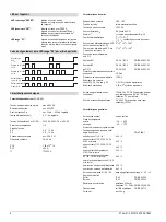
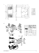
Fig. I
Dimension diagram (dimensions in mm)
Fig. II
Installation instructions
Fig. III
Derating curve
Fig. IVa
Connection example single-phase
Fig. IVb
Connection example three-phase
The terminals X1 - X2 - X3 are not electrically isolated with respect to measuring cir-
cuit L1 - L2 - L3. They therefore have to be driven with floating contacts.
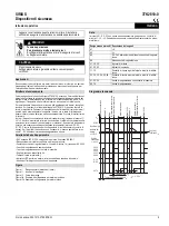
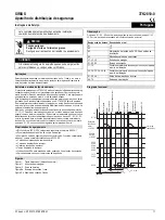
Read and understand these instructions before installing,
operating, or maintaining the equipment.
DANGER
Hazardous voltage.
Will cause death or serious injury.
Turn off and lock out all power supplying this device before
working on this device.
CAUTION
Reliable functioning of the equipment is only ensured with
certified components.
Applications
Design and operating principle
Device features
Figures
!
Note
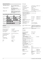
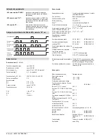
Terminal designation Signal description
A1
+/L
A2
–/L
A3
24 V DC voltage supply signaling outputs
A4
Signaling outputs frame
L1, L2, L3
Measuring inputs
X1, X2, X3
Control terminals
11, 12
Positively driven NC contacts enabling circuit
23, 24; 33, 34; 43, 44
Positively driven NO contacts enabling circuit
51, 52, 54
Changeover contact signaling output
64, 74
Signaling outputs
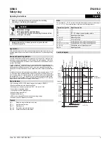
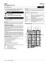
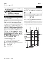
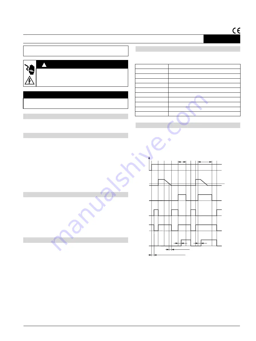
Function diagram
$
$
$$
+
8
6WRS
5HVHW
;
;
5HVHW
;
;
6WUDQGEUHDN
6WUDQGEUHDN
0RWRUVWDQGVWLOOGHWHFWHG
0RWRUFRDVWV
0RWRUFRDVWV
0RWRU2Q
0RWRU2Q
$X[YROWDJH2Q
///
0RWRU
VSHHG
YROWDJH
///
6WUDQGEUHDN
7HVWWLPHGXULQJVZLWFKRQ8
+
9ROWDJH
WKUHVKROG8
DQ
6WDQGVWLOOWLPHW
6
W
(
V
W
(
W
(


