Accessories
4.8 Residual current devices
3VA molded case circuit breakers
356
Manual, 04/2015, A5E03603177010-02
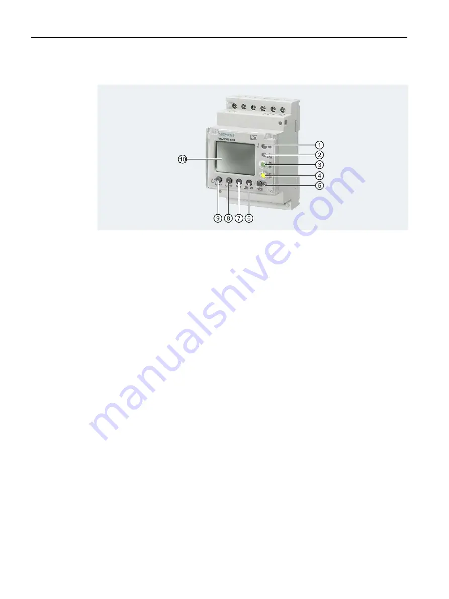
Front view
①
LED ready to operate and tripped display
②
LED alarm display
③
Reset button
④
Test button
⑤
Setting button for alarm/frequency
⑥
Setting button for auto (reclose) for alarm
⑦
Setting button for factory setting (0.03 A, instantaneous)
⑧
Setting button for residual current
⑨
Setting button for non-tripping time
⑩
Display
Description of front panel view
Display of ready-to-operate and tripped and alarm states
The status of LED
①
indicates whether the device is ready to operate or has tripped:
●
Green LED: The device is in operation.
●
Red LED: The set residual current has exceeded the response current, the device has
tripped.
LED
②
is an alarm indication:
●
Yellow LED: The set residual current has exceeded the response current alarm threshold.
Parameterization of the MRCD
For a description of MRCD parameterization procedures and other operating options, please
refer to the operating instructions for the unit.
Summary of Contents for 3VA1 100 A
Page 1: ......
Page 2: ......
Page 518: ...Conversion tables 3VA molded case circuit breakers 518 Manual 04 2015 A5E03603177010 02 ...
Page 531: ...Index 3VA molded case circuit breakers Manual 04 2015 A5E03603177010 02 531 ...
Page 532: ......


