6
Deutsch
English
Français
Betätigung
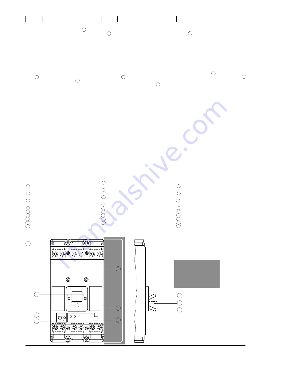
Schaltstellungen und Anzeige siehe Bild 14 .
Sofern kein Drehantrieb montiert wird (ggf. betref-
fende Montageanleitung beachten), wird der Leis-
tungsschalter mit dem Kipphebel betätigt.
Zur leichteren Betätigung ist eine Kipphebelverlänge-
rung vorgesehen, die im Lieferumfang enthalten ist.
Diese wird auf dem Kipphobel aufgesteckt und mit
der mitgelieferten Schraube befestigt.
Der Schaltzustand wird durch die Stellung des Kipp-
hebels 19 angezeigt. Als zusätzliche Schaltstellungs-
anzeigen erscheinen in 2 Fenstern 15 rechts und
links vom Kipphebel drei unterschiedliche Farbsym-
bole:
• Rot (EIN)
• Weiß (Tripped)
• Grün (AUS)
Nach einer Auslösung des Leistungsschalters (Kipp-
hebel in Stellung "Tripped") muß der Kipphebel über
die Stellung "O" (AUS) hinaus bis zur Verklinkung
(RESET) betätigt werden. Erst dann kann der Leis-
tungsschalter wieder eingeschaltet werden. Durch
Betätigen der Taste "Test" läßt sich bei eingeschal-
tetem Leistungsschalter eine mechanische Auslö-
sung (als Funktionsprüfung) bewirken.
Achtung!
Bei einem eingebauten Unterspannungs-
auslöser muß dieser an Spannung liegen, andern-
falls läßt sich der Leistungsschalter nicht einschal-
ten!
Nach einer thermischen Überlastauslösung läßt sich
der Leistungsschalter erst nach einer Abkühlpause
von einigen Minuten wieder einschalten.
15 Schaltstellungsanzeige durch Farben
16 Einstellknopf für den Einstellstrom
I
r
17 Elektronischer Überstromauslöser
18 Isolierstoffgehäuse
19 Kipphebel
20 Taste "Test"
21 EIN (ON)
22 Ausgelöst (Tripped)
23 AUS (OFF) (RESET)
Operation
For toggle handle position and state indication, see
Fig. 14 .
Unless a rotary drive is fitted (if applicable, follow the
mounting instructions), the circuit-breaker is oper-
ated by the toggle handle.
A toggle handle extension is supplied with the cir-
cuit-breaker to facilitate the operation. This is plugged
onto the toggle handle and fixed by means of the
screw supplied.
The switch state is indicated by the position of the
toggle handle 19 . As additional state indication,
three coloured symbols appear in the two windows
of the left and right of the toggle handle 15 :
• Red (ON)
• White (Tripped)
• Green (OFF)
After the circuit-breaker has tripped (toggle handle in
"Tripped" position), the toggle handle must be moved
beyond the 0 ("OFF") position until it relatches (RE-
SET). Only then can the circuit-breaker be reclosed.
By depressing the "Test" button, a closed circuit-
breaker can be mechanically tripped (function test).
Caution!
If an undervoltage release has been in-
stalled, this must be energized, otherwise the circuit-
breaker cannot be closed!
After a tripping operation owing to thermal overload,
the circuit-breaker can only be closed after a cooling
period of several minutes.
15 Switch state indication by colours
16 Adjustment button for current setting
I
r
17 Solid-state overcurrent trip unit
18 Insulating housing
19 Toggle handle
20 "Test" button
21 I (ON)
22 Tripped
23 0 (OFF) (RESET)
Manoeuvre
Positions de manoeuvre et indicateurs de position,
voir Fig. 14 .
Lorsque le disjoncteur n'est pas équipé d'une com-
mande rotative (voir éventuellement instructions de
montage correspondantes), il est actionné à l'aide
de la manette de commande.
Afin de faciliter la manoeuvre, un prolongateur de
manette est joint à la livraison. Le prolongateur de
manette s'enfonce sur la manette (fixation à l'aide
des vis jointes).
La position de la manette 19 indique la position de
manoeuvre. En plus de cela, les 2 échancrures 15
situées de part et d’autre de la manette laissent
appare icre des plages de couleur différente en
fonction de la position du disjoncteur:
• rouge (EN)
• blanc (déclenché)
• vert (HORS)
Lorsque le disjoncteur a déclenché (manette en
position "tripped"), la manette doit être amenée en
position "O" (Hors) jusqu’au déclic (RESET). Le
disjoncteur peut ensuite être refermé. La touche
"Test", permet d'effectuer un essai de déclenche-
ment du disjoncteur.
Attention!
Les disjoncteurs à déclencheur à mini-
mum de tension incorporé ne peuvent être fermés
que lorsque ce déclencheur est sous tension.
Après un déclenchement thermique de surcharge, le
disjoncteur ne peut être refermé qu'après une pé-
riode de refroidissement de quelques minutes.
15 indicateur de position par couleurs
16 bouton de réglage du courant de réglage
I
r
17 déclencheur électronique à maximum de cou-
rant
18 boîtier en matière isolante
19 manette de commande
20 touche "Test"
21 En (ON)
22 déclenché (Tripped)
23 Hors (RESET)
14
18
15
19
17
20
16
21
22
23
NS1-3093a
-
4-polige Ausführung
-
4-pole version
-
version tétrapolaire
-
esecuzione a 4 poli
-
ejecuación tetrapolar
-
4-poligt utförande
Summary of Contents for 3VF7
Page 11: ...11 ...


