Communication System Manual
3VF Circuit-Breakers
Copyright Siemens AG 1998. All rights reserved.
Version1.0 (05/98)
22
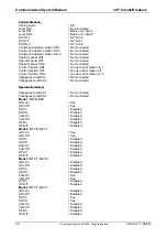
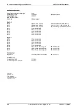
Reset
= Not connected
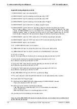
Truth Table 1: 3I1O
I1 I2 I3
= 111 = 0
I1 I2 I3
= 011 = 0
I1 I2 I3
= 101 = 0
I1 I2 I3
= 001 = 1
I1 I2 I3
= 110 = 0
I1 I2 I3
= 010 = 0
I1 I2 I3
= 100 = 0
I1 I2 I3
= 000 = 0
Input I1
= Basic unit, input 3
Auxiliary switch
Input I2
= Basic unit, input 4
Alarm switch
Input I3
= Truth table 2: 3I1O
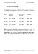
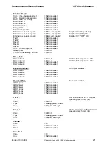
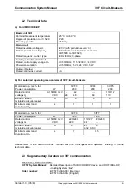
Truth Table 2: 3I1O
I1 I2 I3
= 111 = 0
I1 I2 I3
= 011 = 0
I1 I2 I3
= 101 = 0
I1 I2 I3
= 001 = 0
I1 I2 I3
= 110 = 0
I1 I2 I3
= 010 = 0
I1 I2 I3
= 100 = 1
I1 I2 I3
= 000 = 0
Input I1
= DP bit 0.2
Input I2
= DP bit 0.1
Input I3
= Constant 0
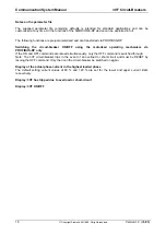
Truth Table 3: 3I1O
I1 I2 I3
= 111 = 1
I1 I2 I3
= 011 = 1
I1 I2 I3
= 101 = 1
I1 I2 I3
= 001 = 0
I1 I2 I3
= 110 = 0
I1 I2 I3
= 010 = 0
I1 I2 I3
= 100 = 0
I1 I2 I3
= 000 = 0
Input I1
= Basic unit, input 3
Input I2
= Basic unit, input 4
Input I3
= DP bit 0.1
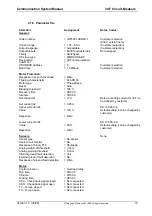
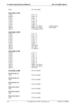
Truth Table 4: 5I2O
= Not connected
Flash Function 1:
Input
= Not connected
Flash Function 2:
Input
= Not connected
Flash Function 3:
Input
= Not connected
Flicker Function 1:
Input
= Not connected
Flicker Function 2:
Input
= Not connected
Flicker Function 3:
Input
= Not connected

