Communication System Manual
3WN6 Circuit-Breakers
Copyright Siemens AG 1998. All rights reserved.
Version1.0 (05/98)
28
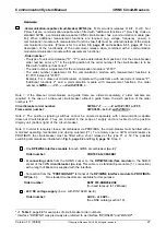
Software:
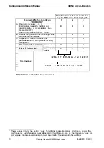
- 3.5" diskette with type/GSD file for the software connection of 3WN6 to PROFIBUS-DP (bus
configuration). This diskette (no. 2b) is supplied with the interface. Step 6, page 34 outlines which
file is to be used for which master.
- Bus master software for communication control. In order to communicate with the SIMATIC S5/S7
as bus master, a standard software block (no. 5) is required (see page 59 for a description of this
module):
Order number:
3RK1800-0AA00-0AA0
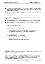
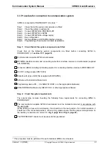
For the initial connection of a 3WN6 circuit-breaker to PROFIBUS-DP, the following hardware and
software components are additionally required:
8
- A programming device (e.g. PG 740), or PC with the appropriate software (e.g. STEP 5) (no. 6)
- COM-PROFIBUS (no. 7) for the 3WN6 software interface (bus configuration) to PROFIBUS-DP.
3.2 Bus connection functionality
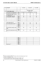
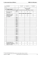
3WN6 output data can be read via PROFIBUS-DP:
- Circuit-breaker key data (e.g. circuit-breaker type/size, overcurrent release version)
- Operational states (e.g. switching state, "Tripped" signals, processor status)
- Operational data (e.g. actual phase current I
L1
)
9
- Protection parameters (e.g. setting current I
r
for overload release)
... and input data can be written to the circuit-breaker:
- Execute switching action (switch circuit-breaker ON or OFF)
- Set protection parameters (e.g. setting current I
r
for overload release)
- Set additional functions (e.g. switch phase sensitivity ON/OFF)
8
With SIMATIC S5 as master. Use appropriate hardware and software components specified by the
supplier for other, especially non-Siemens, masters.
9
Because of the way current transformers work, only currents at the communication module (Z=F01)
which are greater than 18 % of the rated circuit-breaker current (I
n
) are displayed on the release or
transferred via the bus. I = 0 applies below 18 %. Transfer always takes place in the case of the
communication module with measurement functions (Z=F05). The measuring accuracy (above 18 % I
n
)
is +/-5 % of the measured value for the communication function (Z=F01) and +/-3 % of the measured
value for the measurement function (Z=F05). Below 18 % I
n
. (at the measurement module), the
measured values are not identified due to "noise".

