Communication System Manual
3WN6 Circuit-Breakers
Version 1.0 (05/98)
Copyright Siemens AG 1998. All rights reserved.
37
3.4 Displaying the data in the 3WN6 circuit-breaker
3.4.1 Addressing the 3WN6 functions on PROFIBUS-DP:
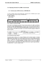
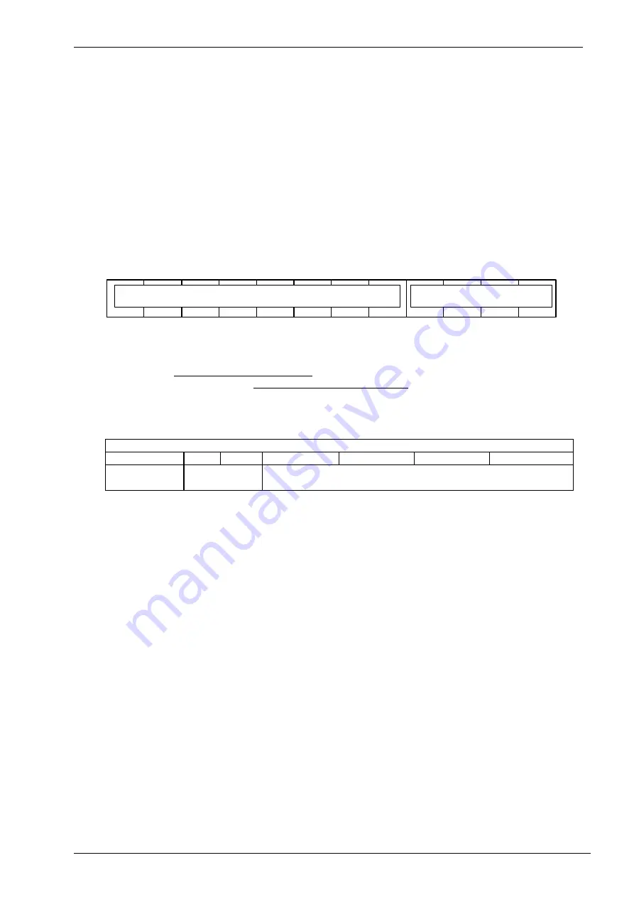
In order to guarantee optimum data transfer times, the large volume of 3WN6 input and output
data is divided into two transfer modes on PROFIBUS-DP
(see Fig. 7, page 37):
- Cyclic transfer and
- Acyclic transfer
8 bytes of acyclic data
4 bytes of cyclic data
1
8
9
12
Fig. 7: 12-byte I/O channel for 3WN6
Cyclic data are automatically transferred at regular intervals between the 3WN6 circuit-breaker
and the PLC. Acyclic 3WN6 data/functions, on the other hand, must be transferred/executed on
PROFIBUS-DP when required by means of a message request. A message request is defined in
the first 8 bytes (or octets) of the PLC I/O area. These message requests initiate execution of the
various functions of the 3WN6 circuit-breaker. The structure of acyclic messages is illustrated in
Fig. 8 on page 37.
Byte (octet)
1 and 2
3
4
5 (= OS1)
6 (= OS2)
7 (= OS3)
8 (= OS4)
Parameter
identifier
Parameter
subindex
Parameter value (integer data value)
Fig. 8: (Acyclic) message requests
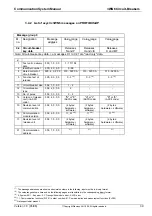
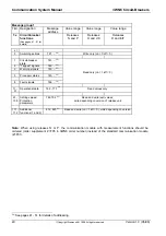
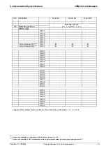
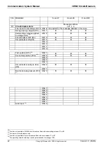
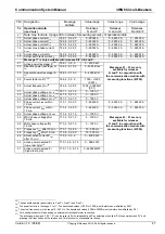
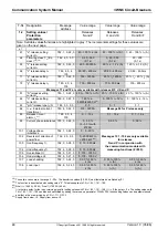
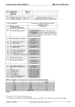
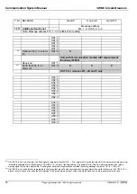
The bytes (octets) relevant for the unique identification of the message request (= message
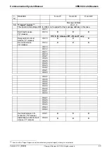
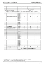
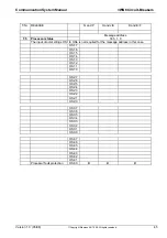
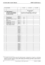
address) are shown on pages 39 - 51. The bytes (octets) shown in Fig. 2 are delimited by commas
(format: bytes 1 and 2, byte 3, byte 4, byte 5, byte 6, byte 7, byte 8). Only the relevant bytes are
shown, e.g. reading the rated current of the circuit-breaker uses bytes (octets) 1 to 6 (message
address = 500, 4, 0, 0, 0). Detailed examples of message requests can be found on page 54,
where you will also find a description of the request identifier, which must be used in addition to
the message address in order to differentiate between read and write requests (request iden
message address = complete message request).

