
Communication System Manual
3WN6 Circuit-Breakers
Version 1.0 (05/98)
Copyright Siemens AG 1998. All rights reserved.
47
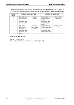
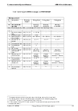
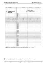
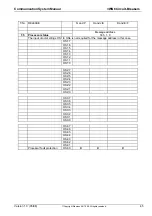
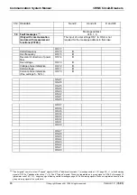
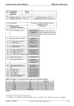
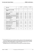
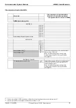
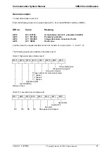
T-Nr. Designation
Message
address
Value range
Value range
Value range
1:x
Operational data
(read only)
Releases
N and P
Releases
H and J/K
Releases
D and E/F
x =
Note: See footnote 9, page 28 for details of measuring accuracy of operational data.
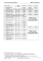
11
Actual phase current I
L1
762, 1, 0, 22, 0
0 - 65532 A
0 - 65532 A
0 - 65532 A
12
Actual phase current I
L2
762, 2, 0, 22, 0
0 - 65532 A
0 - 65532 A
0 - 65532 A
13
Actual phase current I
L3
762, 3, 0, 22, 0
0 - 65532 A
0 - 65532 A
0 - 65532 A
14
Actual max. phase current
L
max
762, 4, 0, 22, 0
0 - 65532 A
0 - 65532 A
0 - 65532 A
16
Actual phase current I
N
762, 6, 0, 22, 0
0 - 65532 A
0 - 65532 A
0 - 65532 A
17
Actual earth fault current I
g
762, 7, 0, 22, 0
0 - 65532 A
0 - 65532 A
0 - 65532 A
Message 17 is only available with releases E/F, J/K and P.
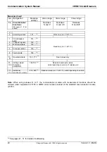
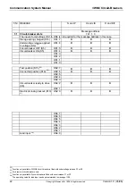
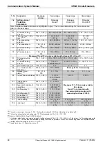
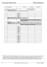
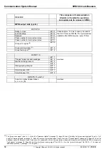
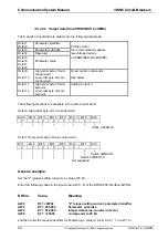
21
Active power (average) P
34)
766, 1, 0, 9, 3
0 - 4000 kW
22
Reactive power (average) Q
34)
766, 2, 0, 10, 3
0 - 4000 kVar
Messages 21 - 33 are only
available for releases
23
Apparent power (average) S
33)
766, 3, 0, 10, 3
0 - 4000 kVA
N and P in conjunction with
the communication module with
24
Power factor cos
ϕ
34)
766, 4, 0, 0, 0
-1000 - +1000
(0.001)
measuring functions (Z=F05).
26
Actual frequency f
act
35
766, 6, 0, 28, 0
1500 - 50000 Hz
(0.01)
31
Actual phase voltage U
L1-L2
36)
767, 1, 0, 21, 0
0 - 1000 V
32
Actual phase voltage U
L2-L3
36)
767, 2, 0, 21, 0
0 - 1000 V
33
Actual phase voltage U
L3-L1
36)
767, 3, 0, 21, 0
0 - 1000 V
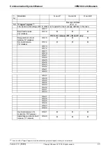
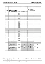
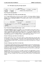
41
Phase current I
MAX
within
15 min
773, 1, 0, 22, 0
0 - 65532 A
0 - 65532 A
0 - 65532 A
42
Phase current I
MIN
within
15 min
773, 2, 0, 22, 0
0 - 65532 A
0 - 65532 A
0 - 65532 A
44
Actual phase voltage U
L, MAX
773, 4, 0, 21, 0
0 - 1000 V
45
MAX phase voltage after
15 min
773, 5, 0, 21, 0
0 - 1000 V
Messages 43 - 51 are only
available for releases
46
MIN phase voltage after
15 min
773, 6, 0, 21, 0
0 - 1000 V
N and P in conjunction with
the communication module with
47
Frequency f
MAX
after 15 min
773, 7, 0, 28, 0
15 - 500 Hz
measuring functions (Z=F05).
48
Frequency f
MIN
after 15 min
773, 8, 0, 28, 0
15 - 500 Hz
49
Actual active current P
max
after 15 min
773, 9, 0, 9, 3
0 - 4000 kW
50
Active power demand P
c
(low-order byte)
37)
773, 10, 0, 8, 75
0 - 999 kWh
51
Active power demand P
c
(high-order byte)
773, 11, 0, 8, 76
0 - 65532 MWh
33)
The handheld operator panel refers to P as P
w
, Q as P
b
and S as P
s
.
34)
The power factor is in the range -1 to +1. The transferred values (-1000 to +1000) must therefore be multiplied by 0.001.
35)
The actual frequency is in the range 15 - 500 Hz. The transferred values (1500 to 50000) must therefore be multiplied by 0.01.
36)
Or to neutral conductor N depending on external current transformer connection.
37)
The active power demand (1:50, 1:51) can be reset to 0 with releases N and P by selecting menu item "Active power demand Pc" and
pressing the Clear button on the release unit. This function is not available via the bus.


