
Communication System Manual
3WN6 Circuit-Breakers
72
Copyright Siemens AG 1998. All rights reserved.
Version 1.0 (02/98)
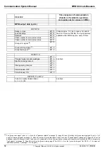
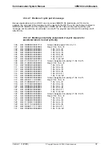
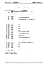
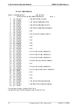
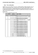
3.5.3.6.2 DB81
DB81 C:BS3WN6ST.S5D LAE=261 /504
3WN6 ASSIGNMENT TO MESSAGE GROUP 1 Sheet 1
0: KF = +00721; 1:000 SWITCHING ACTIONS
1: KY = 001,000;
2: KF = +00741; 1:001 CIRCUIT-BREAKER STATE
3: KY = 001,000;
4: KF = +00742; 1:002 CIRCUIT-BREAKER FAULTS
5: KY = 001,000;
6: KF = +00743; 1:003 CIRCUIT-BREAKER WARNINGS
7: KY = 001,000;
8: KF = +00000; 1:004
9: KY = 000,000;
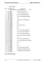
10: KF = +00745; 1:005 STATUS OF MEAS. MODULE
11: KY = 001,000;
12: KF = +00000; 1:006
13: KY = 000,000;
14: KF = +00000; 1:007
15: KY = 000,000;
16: KF = +00748; 1:008 FAULT SIGNALS
17: KY = 001,000;
18: KF = +00000; 1:009
19: KY = 000,000;
20: KF = +00000; 1:010
21: KY = 000,000;
22: KF = +00762; 1:011 ACTUAL PHASE CURRENT L1
23: KY = 001,022;
24: KF = +00762; 1:012 ACTUAL PHASE CURRENT L2
25: KY = 002,022;
26: KF = +00762; 1:013 ACTUAL PHASE CURRENT L3
27: KY = 003,022;
28: KF = +00762; 1:014 MAX ACTUAL PHASE CURRENT
29: KY = 004,022;
30: KF = +00000; 1:015
31: KY = 000,000;
32: KF = +00762; 1:016 ACTUAL PHASE CURRENT N
33: KY = 006,022;
34: KF = +00762; 1:017 ACTUAL EARTH FAULT CURRENT I
35: KY = 007,022;
36: KF = +00000; 1:018
37: KY = 000,000;
38: KF = +00000; 1:019
39: KY = 000,000;
40: KF = +00000; 1:020
41: KY = 000,000;
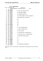
42: KF = +00766; 1:021 ACTIVE POWER [AVERAGE]
43: KY = 001,009;
44: KF = +00766; 1:022 REACTIVE POWER [AVERAGE]
45: KY = 002,001;
46: KF = +00766; 1:023 APPARENT POWER [AVERAGE]
47: KY = 003,001;
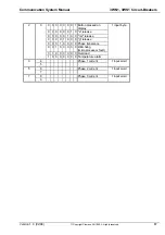
2*T-Nr. = parameter identifier
2*T-Nr.+1 = parameter subindex


