Communication System Manual
3WN1, 3WS1 Circuit-Breakers
Version 1.0 (02/98)
Copyright Siemens AG 1998. All rights reserved.
83
Step 2:
Check the system requirements
The second step involves checking the following three requirements for connecting 3WN1/3WS1 to
PROFIBUS-DP:
•
The communication-capable 3WN1/3WS1 circuit-breaker must be installed and wired in
accordance with the user guide (included in scope of supply of circuit-breaker).
Note
Circuit-breaker position
!
A draw-out circuit-breaker must be in the test position for testing and in the
connected position for normal operation.
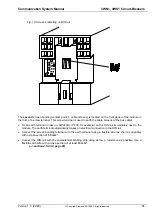
When wiring, please ensure that the jumper arrangements on the auxiliary connectors are correct
(cf. Fig. 15, page 91 and Fig. 15, page 92 in the 3WN1/3WS1 user guide)
•
The PROFIBUS-DP master must be present and operational.
•
The 3RK1002 interface module must be correctly installed and connected (section 4.5.2, page
90).
•
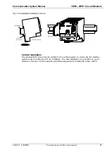
The compact housing of the 3RK1002 interface module is 70 mm wide and can simply be
snapped onto a 35 mm DIN rail. The devices can be mounted side by side.
Note
Installation procedure
!
The interface module must not be mounted directly above the arcing
space of the circuit-breaker, unless suitable covers have been fitted.
•
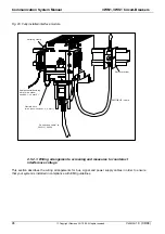
The earth connection of the interface module (shield signal for electronic circuit) is made using a
flexible earth wire (1.5 mm
2
) and an earth terminal (order no. 8WA1001-1PF00, for example)
which is mounted on the DIN rail immediately next to the interface module.
•
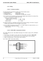
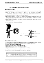
The 9-pin SUB-D socket on the 3WN1/3WS1 circuit-breaker which is used for the connecting
cable between the circuit-breaker and the interface module must be earthed using a flexible
earth wire (2.5 mm
2
).
-The standard length of connecting cable 3WN1/3WS1-3RK1002 between the 3WN1/3WS1 circuit-
breaker and the 3RK1002 interface module is 3 m.
(--> see section 4.5.2.2.5, page 94)

