Communication System Manual
3WN1, 3WS1 Circuit-Breakers
84
Copyright Siemens AG 1998. All rights reserved.
Version 1.0 (08/98)
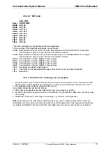
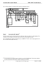
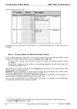
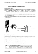
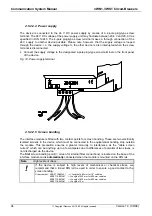
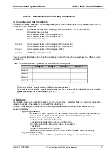
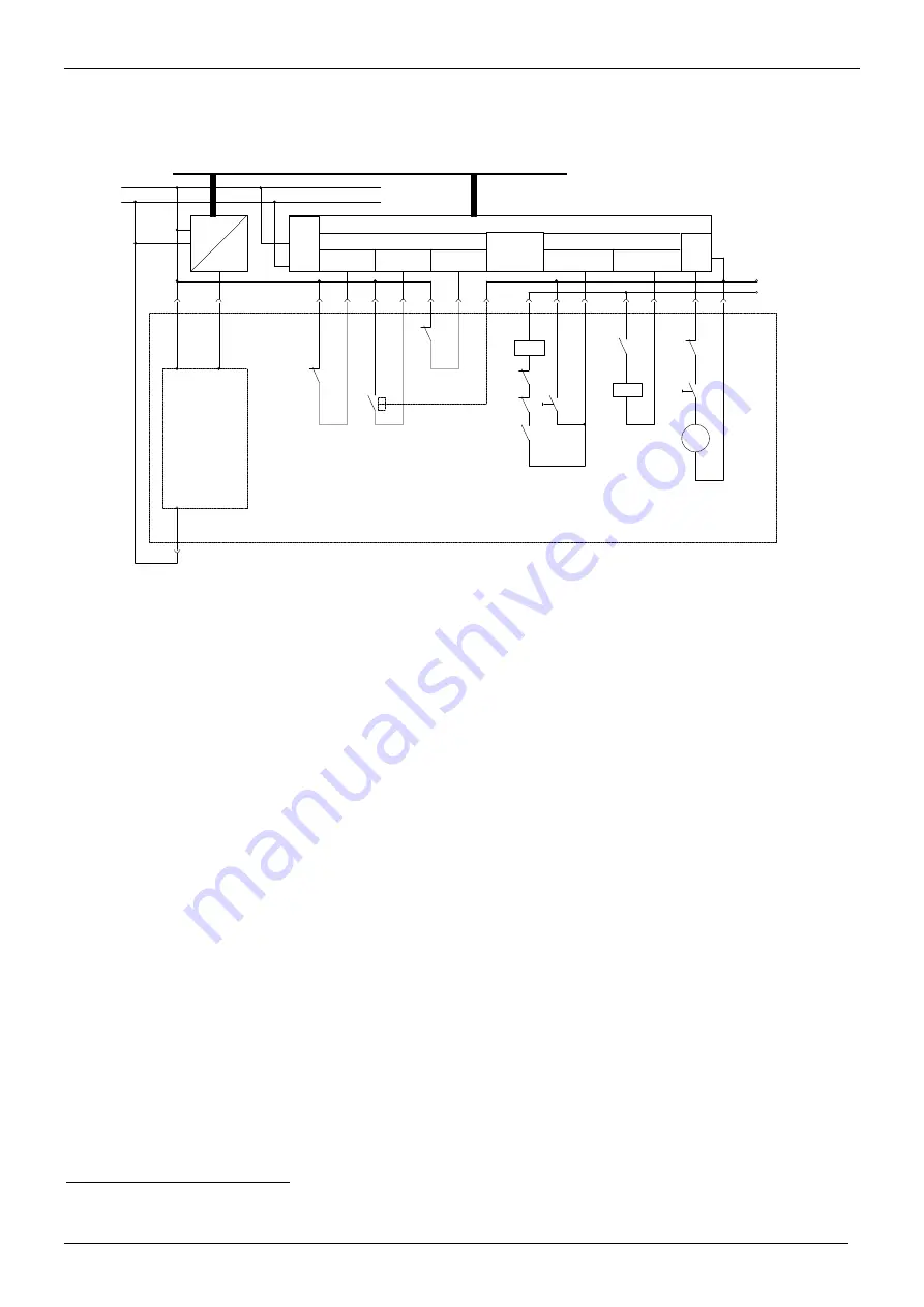
Fig. 13: Wiring example in accordance with the data areas described in Step 7
X6.9
X6.4
X6.10
TTY
Overcurrent release
3WN1 / 3WS1
Type 5
Type 8
X1.7
X1.8
-S5
E n+0
X2.5
X2.6
X2.9
X2.10
E n+1
E n+2
switching
status
-K1
ready to close
-S9
spring charge
status
DC 24V
-S7
-S23
-S8
-Y1
Closing solenoid
for ON-command
-S21
A n+0
X3.2
X3.6
X3.9
-F1
-S6
A n+1
-S8
-S21
M
X1.9
X1.10
X3.3
X3.4
0V
ET 200 U
6ES5 450-8MD11
6ES5 431-8MA11
L1
N
230 V~
Profibus DP
circuit-breaker 3WN1 / 3WS1
3RK1002
Profibus DP
1
2
1
2
X3.1
Shunt release
N
L1
3
5
2
1
4
3
6
2
1
for OFF-command
Step 3:
Connect the I/O module
57
Wire the required input and output modules for the digital bus inputs and outputs. The output signals of the
modules must be configured in accordance with the levels of the circuit-breaker actuators.
Fig. 13 illustrates this connection with reference to a SIMATIC ET 200 U with an input signal level of
24 V DC and an output signal of 230 V AC.
57)
This assumes that conventional copper conductors are used for PROFIBUS-DP. If fiber optic conductors
are used, converters from fiber optic to copper conductors must be fitted.


