Communication System Manual
3VF Circuit-Breakers
Version 1.0 (05/98)
Copyright Siemens AG 1998. All rights reserved.
9
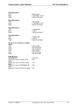
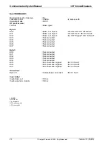
PROFIBUS-DP uses different data channels in order to maintain fast transmission times. In this way, up to
12 bytes can be transferred at regular intervals from SIMOCODE-DP to the automation level and up to 4
bytes can be transferred back.
The 20 bytes of diagnostic data are only transferred from SIMOCODE-DP to the automation level in the
event of a change, i.e. the diagnostic channel is event-triggered. The 213 bytes of parameter data are only
transferred to SIMOCODE-DP when the automation system is started up.
SIMOCODE-DP can operate in conjunction with any standard PROFIBUS-DP master which is capable of
reading type or GSD files and which can process the following volumes of data:
•
4 bytes of control data cyclically from the DP master to SIMOCODE-DP
•
4 or 12 bytes of signal data cyclically from SIMOCODE-DP to the DP master
•
20 bytes of diagnostic data acyclically from SIMOCODE-DP to the DP master
•
213 bytes of parameter data
In order to guarantee optimum data transfer times, the large volume of SIMOCODE-DP input and output
data is divided into two transfer modes on PROFIBUS-DP - cyclic and acyclic transfer modes:
1. Cyclic data traffic: cyclic data (e.g. actual maximum phase current I
Lmax
in the highest loaded phase)
correspond to basic information which is transferred at regular intervals. Important information is
automatically transferred from the circuit-breaker to the I/O area of the bus master in this way. Similarly
all the important (cyclic) data contained in the I/O area of the bus master are also transferred to the
circuit-breaker.
Cyclic input data include, for example, the setting current value for overload releases (setting current
I
r
), as well as the circuit-breaker remote ON/OFF command. Cyclic output data from SIMOCODE-DP
include the switching state of the circuit-breaker (ON/OFF), as well as various group signals which can
indicate whether a fault (e.g. trip due to overload or short-circuit) or a warning (e.g. current warning,
80 % or 120 %) is present.
2. Acyclic data traffic: Acyclic data are only transferred from the interface to the bus master or from the
bus master to the circuit-breaker when a request is transmitted. This means that specific messages are
sent from the bus master to the 3VF circuit-breaker when required.


