
Communication System Manual
3WN1, 3WS1 Circuit-Breakers
90
Copyright Siemens AG 1998. All rights reserved.
Version 1.0 (08/98)
€
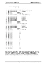
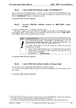
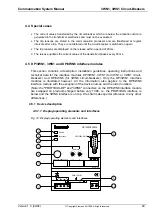
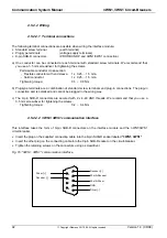
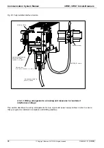
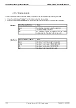
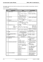
Device status LED:
green
à
Device OK
red
à
Device defective
off
→
Device switched off
•
Interface status LED:
green
à
Both communication interfaces OK
yellow
à
Communication interface 1 not clear (PROFIBUS-DP)
off
à
Communication interface 2 not clear (3WN1/3WS1)
red
à
Communication interfaces both not clear
‚
not configured
ƒ
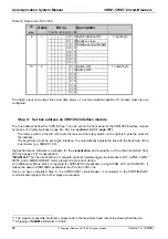
Address switch for PROFIBUS-DP
(addresses 0 ... 99)
„
not configured
…
Inscription plates
†
Earth terminal for cable screens
‡
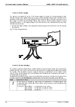
Power supply terminals
ˆ
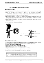
Communication interface 1:
à
PROFIBUS-DP
(9-pin SUB-D socket)
‰
Communication interface 2:
à
3WN1, 3WS1
(9-pin SUB-D socket)
Š
not configured
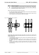
4.5.2 Installation guidelines
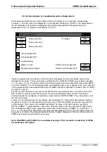
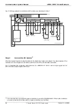
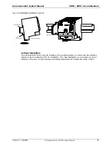
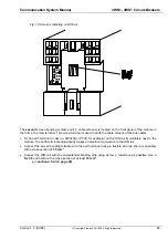
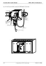
4.5.2.1 Installing the interface module
The interface module is designed for installation in a switchgear cubicle (IP20) and can therefore only be
mounted on a standard DIN rail (deep rail in acc. with EN50022)
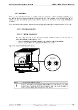
Installation
•
Lower the module onto the DIN rail from above.
•
Then swivel it downwards until the slide mechanism on the module snaps onto the rail.
•
You may install other modules on the rail to the left and right of the interface module.
•
Clearance of at least 5 cm must be provided above and below the module to allow for heat dissipation.
•
Connect the standard DIN rail to the equipotential bonding strip of the switchgear cubicle. The
connecting wire must have a cross-section of at least 10 mm
2
.
•
Install an earth terminal immediately next to the interface module so that the flexible wire (1.5 mm
2
)
used for screen bonding can be as short as possible.
Deinstallation
•
First disconnect the power supply and signal cables.
•
Then use a screwdriver to press the slide mechanism on the module downwards.
•
Now swivel the module off the DIN rail.


