6
4 Anlagentür und Einschubrahmen vorbe-
reiten
4.1
Anlagentür vorbereiten
Türausschnitt und Befestigungslöcher siehe Maßbilder im
Katalog und im Handbuch.
Die Montage des Sichtfensters 4.51 (Fig. 7) ist nach der Be-
triebsanleitung 9239 9735 174 vorzunehmen.
4 Preparing the cubicle door and guide
frame
4.1
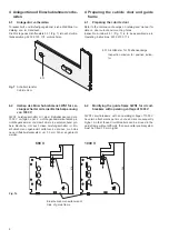
Preparing the cubicle door
Refer to the dimension drawings on catalog and manual for
data on door cutout and mounting holes
Inspection window 4.51 (Fig. 7) is to be assembled as in
Operating instructions 9239 9735 174.
Fig. 7
Schaltschranktür
Cubicle door
4.51 Sichtfenster für Positionsanzeige
Inspection window for position indica-
tor
4.51
4.2
Umbau des Einschubrahmens 3WN1 für Lei-
stungsschalter mit einer Betriebsspannung
von 1000 V
3WN1 Leistungsschalter mit einer Betriebsspannung von
1000 V verfügen über 2 Lichtbogenkammeraufsätze pro
Lichtbogenkammer und damit über eine entsprechend grö-
ßere Bauhöhe. Um auch diese Leistungsschalter im Ein-
schubrahmen ungehindert verfahren zu können, muß das
neue Hilfsleiterstecksystem um 30 mm höher angebracht
werden.
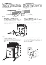
4.2
Modifying the guide frame 3WN1 for circuit-
breakers with operating voltage of 1000 V
3WN1 circuit-breakers with an operating voltage of 1000 V
have two attachments per arc chute and are consequently
higher. So that these circuit-breakers can be moved in the
guide frame without difficulty, the new auxiliary cable system
must be fitted 30 mm higher.
545
515
Einschubrahmenseitenwand/
Side of guide frame
690 V
1000 V
Fig. 7a


