8 – 82
3ZW1012-0WL11-0AB1
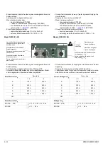
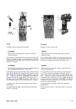
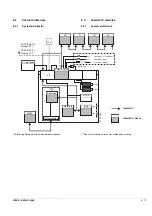
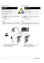
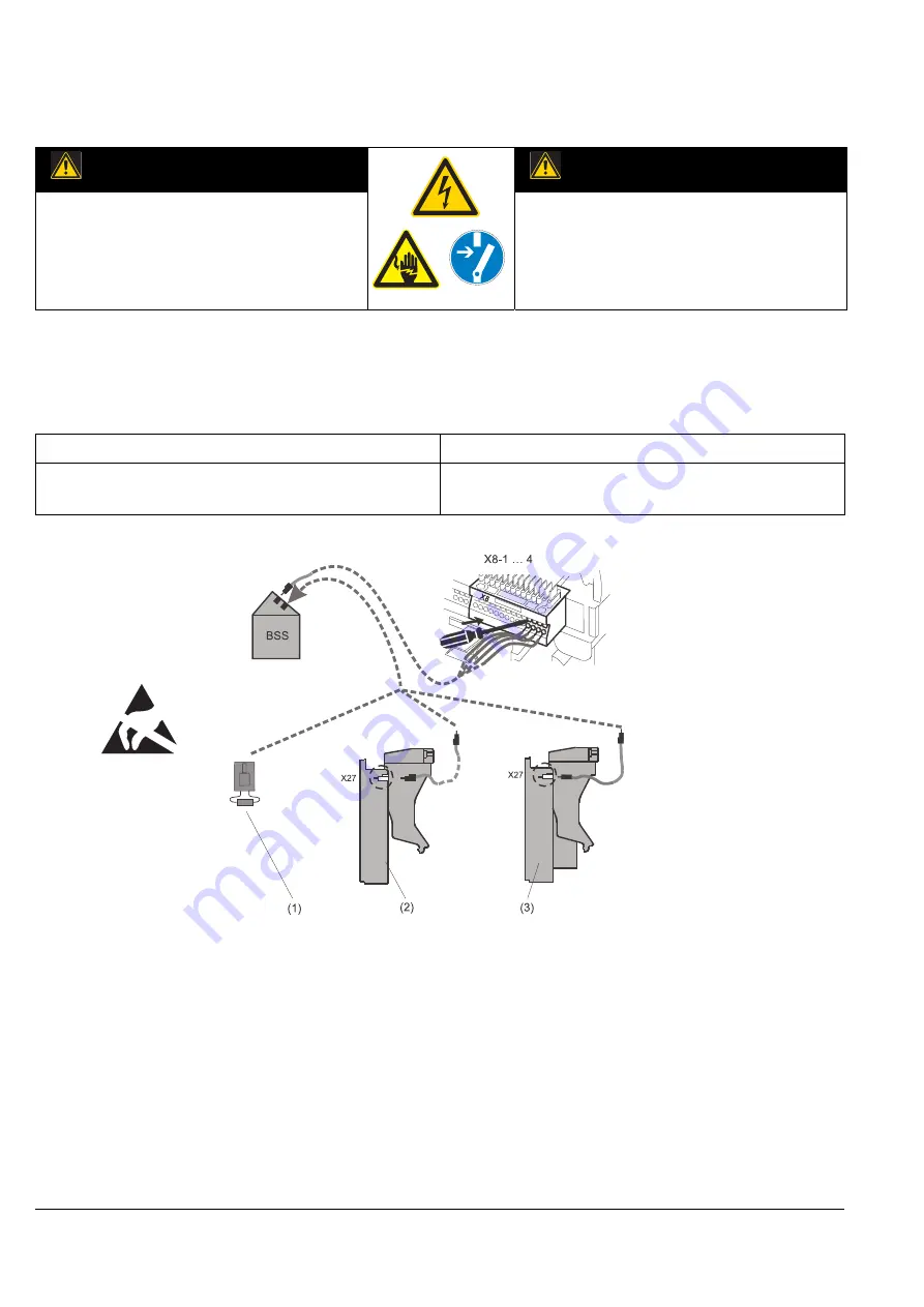
Connecting BSS-module
The first
c
connection leads to receptacle X8. The
second
c
connection is performed according to the cir-
cuit breaker equipment.
→
Circuit diagrams
(1)
Terminating resistor in the BSS for
ETU15B ... 27B or for non-automatic air circuit breakers
(2)
ETU45B ... 76B without metering function
(3)
ETU45B ... 76B with metering function
BSS-Modul anschließen
Der erste
c
-Anschluss führt an die Messerleiste X8. Der
zweite
c
-Anschluss erfolgt je nach Ausstattung des Lei-
stungsschalters.
→
Schaltpläne
(1)
Abschlusswiderstand in der BSS für den ETU-Abgang bei
ETU15B … 27B oder bei Leistungstrennschaltern
(2)
ETU45B … 76B ohne Messfunktion
(3)
ETU45B … 76B mit Messfunktion
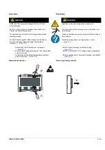
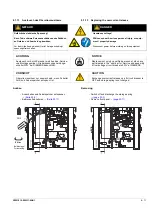
GEFAHR
DANGER
Gefährliche elektrische Spannung!
Kann Tod, schwere Personenschäden sowie Schäden
an Geräten und Ausrüstung bewirken.
Vor dem Arbeiten an diesem Gerät, Anlage unbedingt
spannungsfrei schalten.
Hazardous voltage!
Will cause death, serious personal injury, or equip-
ment / property damage.
Disconnect power before working on this equipment.
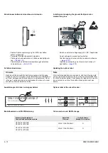
Hinweis
Note
Ggf. fehlende Hilfsstromanschlüsse nachrüsten (Messerleiste,
Hilfsstromstecker, Schleifkontaktmodul für Einschubrahmen).
→
If necessary missing auxiliary terminals may be retrofitted
(receptacle, auxiliary connectors and sliding contact module for
guide frames).
→
Summary of Contents for 3ZW1012-0WL11-0AB1
Page 15: ...3ZW1012 0WL11 0AB1 0 XV ...
Page 87: ...3ZW1012 0WL11 0AB1 8 15 S Auslösung I Auslösung S tripping I tripping ...
Page 88: ...8 16 3ZW1012 0WL11 0AB1 Erdschlussauslösung Ground fault tripping ...
Page 359: ...3ZW1012 0WL11 0AB1 27 5 ...
Page 360: ...27 6 3ZW1012 0WL11 0AB1 ...
Page 366: ......
Page 367: ......

