8 – 112
3ZW1012-0WL11-0AB1
Anzeigen
→
Testen
→
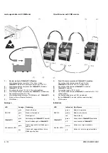
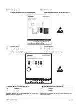
8.2.3.4 Digitale Ausgangsmodule
Funktion
Mit digitalen Ausgangsmodulen können bis zu 6 Meldungen ausge-
geben werden.
Meldet der Überstromauslöser ein Ereignis, leuchtet nach Ablauf
der eingestellten Verzögerungszeit die zum Ereignis gehörende
LED auf und das Modul setzt ein Signal am entsprechenden Aus-
gang.
Digitale Ausgangsmodule stehen in folgenden Ausführungen zur
Verfügung:
- mit Drehkodierschalter und Relaisausgängen
- konfigurierbar und mit Relaisausgängen.
Montage
→
Anschluss
→
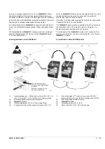
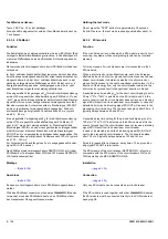
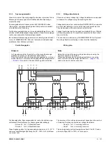
Verbindungsaufbau
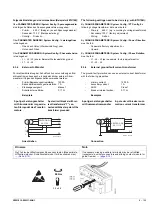
Sollen digitale Ausgangsmodule mit Drehkodierschalter und konfi-
gurierbare digitale Ausgangsmodule gemeinsam an einem Lei-
stungsschalter angeschlossen werden, können pro
Leistungsschalter angeschlossen werden:
- 1 digitales Ausgangsmodul mit Drehkodierschalter
und Ausgangsbelegung 1
- 1 digitales Ausgangsmodul mit Drehkodierschalter
und Ausgangsbelegung 2
- 1 konfigurierbares digitales Ausgangsmodul
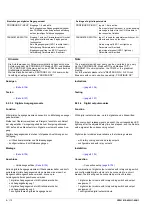
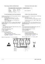
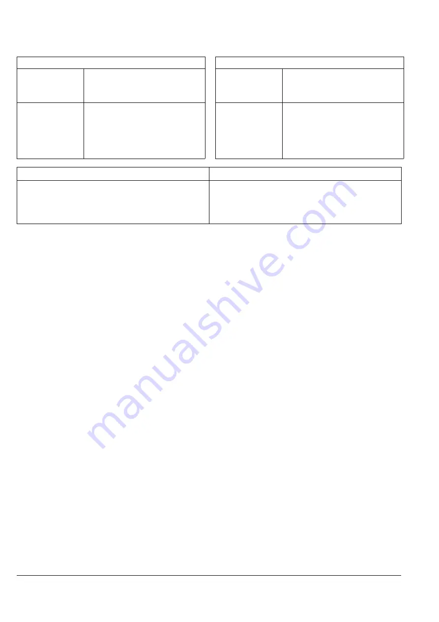
Einstellungen digitales Eingangsmodul
PROFIBUS DP
INPUT Eingänge 1-6 sind aktiv.
Bei Anliegen eines Eingangssignals wird über
das COM-Modul eine entsprechende Meldung
auf den jeweiligen Feldbus ausgegeben
PARAMETER SWITCH Eingang 1 wird zur Parametersatz-Umschal-
tung genutzt, alle anderen Eingänge sind
funktionslos.
Kein Eingangssignal (LED 1 leuchtet nicht):
Anforderung Parametersatz A aktiviert
Eingangssignal liegt an (LED 1 leuchtet):
Anforderung Parametersatz B aktiviert
Hinweis
Note
Die Anforderungen zur Parameterumschaltung kann durch eine
Anforderung über die PROFIBUS DP, Modbus RTU und Modbus
TCP / PROFINET IO-Kommunikation, den TD400 oder über das
Grafikdisplay überstimmt werden.
Weitere Einzelheiten siehe „SENTRON 3WL / 3VL kommunika-
tionsfähige Leistungsschalter - PROFIBUS DP“
The parameter switchover query can be overruled by a query
via the PROFIBUS DP, Modbus RTU and Modbus TCP /
PROFINET IO-communication, the TD400 or the graphical
display.
For further details please refer to "SENTRON 3WL / 3VL Circuit
Breakers with communication capability - PROFIBUS DP”.
Indications
→
Testing
→
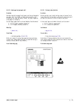
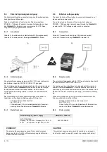
8.2.3.4 Digital output modules
Function
With digital output modules, up to 6 signals can be transmitted.
If the overcurrent release signals an event, the corresponding LED
lights up after the adjusted delay time has elapsed, and the module
sets a signal at the corresponding output.
Digital output modules are available in the following versions:
- with rotary coding switch and relay outputs
- configurable and with relay outputs
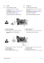
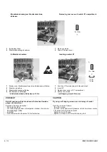
Installation
→
Connection
→
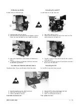
Connection setup
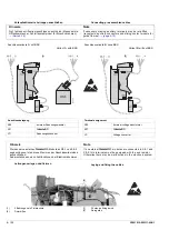
If a combination of digital output modules with rotary coding switch
and configurable digital outputs is to be connected to a circuit
breaker, the following can be connected per circuit breaker:
- 1 digital output module with rotary coding switch and output
assignment 1
- 1 digital output module with rotary coding switch and output
assignment 2
- 1 configurable digital output module
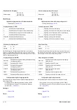
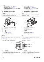
Settings of digital input module
PROFIBUS DP
INPUT Inputs 1-6 are active.
If an input signal is present, a corresponding
message is output via the COM module to
the respective fieldbus
PARAMETER SWITCH Input 1 is used for parameter switchover. All
other inputs have no function.
No input signal (LED 1 not lights up):
Parameter set A actived
Input signal present (LED 1 lights up):
Parameter set B actived
Summary of Contents for 3ZW1012-0WL11-0AB1
Page 15: ...3ZW1012 0WL11 0AB1 0 XV ...
Page 87: ...3ZW1012 0WL11 0AB1 8 15 S Auslösung I Auslösung S tripping I tripping ...
Page 88: ...8 16 3ZW1012 0WL11 0AB1 Erdschlussauslösung Ground fault tripping ...
Page 359: ...3ZW1012 0WL11 0AB1 27 5 ...
Page 360: ...27 6 3ZW1012 0WL11 0AB1 ...
Page 366: ......
Page 367: ......

