3ZW1012-0WL11-0AB1
8 – 107
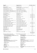
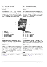
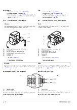
Einstellprinzip
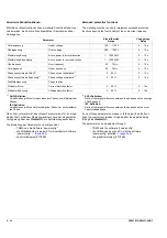
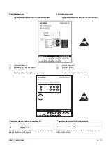
Modultest
Die korrekte Funktion der
c
-Module kann im Test-Modus
überprüft werden.
Einmaliges Betätigen der Taste „TEST“ startet den Test-Modus.
Alle Ausgänge und die dazu gehörenden LEDs werden ausgeschal-
tet. Die Farbe der DEVICE-LED wechselt von grün auf gelb.
Prüfen der Ein- und Ausgänge
Mehrmaliges Betätigen der Taste „TEST“ kurz hintereinander
bewirkt bei eingeschalteter LED abwechselndes Ein- und Ausschal-
ten des jeweiligen Ein- / Ausgangs.
Prüfen nur der LEDs
Bei mehrmaligem Betätigen der Taste „TEST“ mit einer Pause
dazwischen werden nur die LEDs einzeln nach einander einge-
schaltet. Nach der letzten LED werden alle LED eingeschaltet.
Abermaliges Betätigen der Taste „TEST“ startet den Test-Modus von
vorn und alle LEDs sowie Ein- / Ausgänge werden ausgeschaltet.
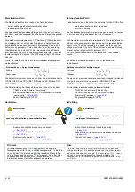
VORSICHT
CAUTION
Bei der Anlagenprojektierung und Selektivitätsbetrachtung ist
sicherzustellen, dass der Leistungsschalter nicht Ströme führen
kann, die oberhalb der im Katalog angegebenen Schaltleistungs-
werte liegen.
Übergeordnete Schutzgeräte sind so einzustellen, dass diese
Fehlerfälle sicher abgeschaltet werden.
When planning a project and considering selectivity it has to be
ensured loads carried by the circuit-breaker will not exceed the
breaking capacity stated in the 3WL catalogue.
Upstream protection equipment has to be set in a way, that
these faults are interrupted safely.
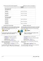
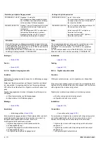
Betätigen der Taste
„TEST“
Wirkung
2 x kurz hintereinander - LED 1 und Ein- / Ausgang 1 ein
Nach Pause,
2 x kurz hintereinander
- LED 1 und Ein- / Ausgang 1 aus,
- LED 2 und Ein- / Ausgang 2 ein
Nach Pause,
2 x kurz hintereinander
- LED 2 und Ein- / Ausgang 2 aus,
- LED 3 und Ein- / Ausgang 3 ein
...
...
Nach Pause,
2 x kurz hintereinander
- LED 5 und Ein- / Ausgang 5 aus,
- LED 6 und Ein- / Ausgang 6 ein
Nach Pause, 1x
Ein- / Ausgang 6 aus, alle LEDs ein
1x
Test-Modus beginnt von vorn, alle Ein- / Aus-
gänge und die dazu gehörenden LEDs sind aus
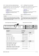
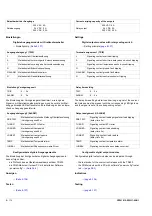
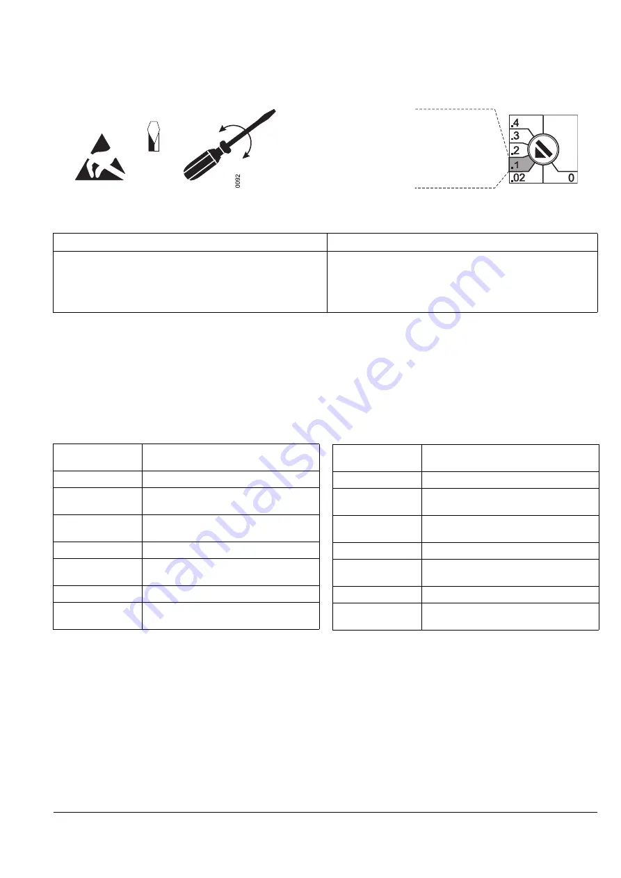
Der Wert 0,1 ist eingestellt,
wenn der Drehschalter
in diesem
Drehwinkelbereich
steht
The value 0.1 is set if the
rotary switch is positioned in this
zone
3 x 0,5
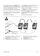
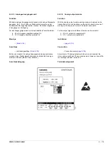
Setting principle
Module test
The correct operation of the
c
-modules can be verified in
the test mode.
The test mode is started by pushing the “TEST” button once.
All outputs and the associated LED's are switched off. The colour of
the DEVICE LED changes from green to yellow.
Testing inputs and outputs
Pushing the "TEST" button several times in quick succession when
an LED is on switches the respective input/output on and off alter-
nately.
Testing LED's only
Pushing the "Test" button several times with pauses in between
switches the LEDs on successively. After the last LED, all LEDs are
switched on.
Repeated pushing the “TEST” button starts the test mode again,
and all LEDs, inputs and outputs are switched off.
Pressing the “TEST”
Button
Reaction
Twice quickly
- LED 1 and Input/output 1 on
After a pause,
twice quickly
- LED 1 and input/output 1 off,
- LED 2 and Input/output 2 on
After a pause,
twice quickly
- LED 2 and input/output 2 off,
- LED 3 and Input/output 3 on
...
...
After a pause,
twice quickly
- LED 5 and input/output 5 off,
- LED 6 and Input/output 6 on
After a pause, once
Input/output 6 off, all LEDs on
Once
Test mode starts again, all inputs/ouputs and
the associated LED‘s are off
Summary of Contents for 3ZW1012-0WL11-0AB1
Page 15: ...3ZW1012 0WL11 0AB1 0 XV ...
Page 87: ...3ZW1012 0WL11 0AB1 8 15 S Auslösung I Auslösung S tripping I tripping ...
Page 88: ...8 16 3ZW1012 0WL11 0AB1 Erdschlussauslösung Ground fault tripping ...
Page 359: ...3ZW1012 0WL11 0AB1 27 5 ...
Page 360: ...27 6 3ZW1012 0WL11 0AB1 ...
Page 366: ......
Page 367: ......

