16 – 5
3ZW1012-0WL11-0AB1
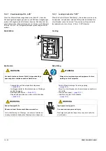
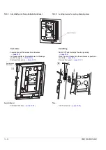
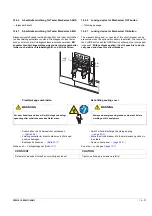
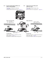
16.2.1.2 Draw-out circuit breaker
- OPEN the circuit breaker and discharge the storage
spring
- Remove the breaker from the guide frame
Then:
- Insert the draw-out circuit breaker into the guide frame,
push into disconnected position
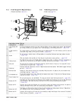
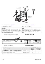
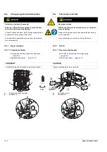
16.2.2
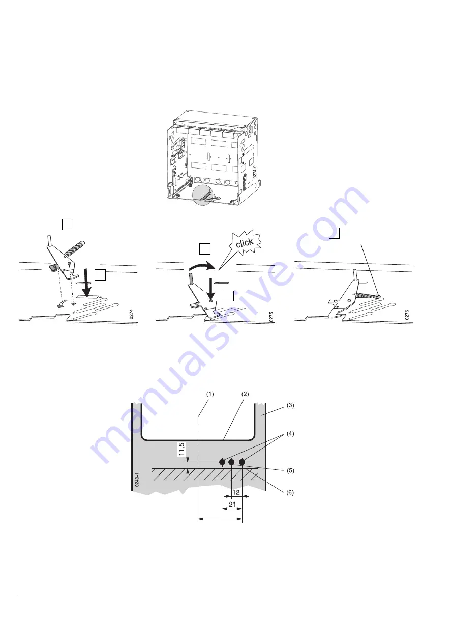
Cubicle door interlock drill pattern
(1)
Centre of front panel
(2)
Door cutout for front panel
(3)
Inner side of cubicle door
(4)
2 mounting holes Ø 5.5 mm
(5)
Hole for outwitting Ø 5.5 mm
(6)
Mounting surface
16.2.1.2 Einschubschalter
- Leistungsschalter ausschalten und Federspeicher ent-
spannen
- Einschubschalter aus Einschubrahmen entnehmen
Anschließend:
- Einschubschalter in Einschubrahmen einsetzen, in Trenn-
stellung schieben
q
16.2.2
Schaltschranktür bohren
(1)
Mitte Bedienpult
(2)
Türausschnitt für Bedienpult
(3)
Innenseite Schaltschranktür
(4)
2 Befestigungsbohrungen Ø 5,5 mm
(5)
Öffnung zum Überlisten Ø 5,5 mm
(6)
Montagefläche
4
5
1
2
3
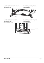
Feder einhängen
Engage tension spring
Feder einhängen
Engage tension spring
andrücken + halten
press + hold
38
Summary of Contents for 3ZW1012-0WL11-0AB1
Page 15: ...3ZW1012 0WL11 0AB1 0 XV ...
Page 87: ...3ZW1012 0WL11 0AB1 8 15 S Auslösung I Auslösung S tripping I tripping ...
Page 88: ...8 16 3ZW1012 0WL11 0AB1 Erdschlussauslösung Ground fault tripping ...
Page 359: ...3ZW1012 0WL11 0AB1 27 5 ...
Page 360: ...27 6 3ZW1012 0WL11 0AB1 ...
Page 366: ......
Page 367: ......

