9 – 92
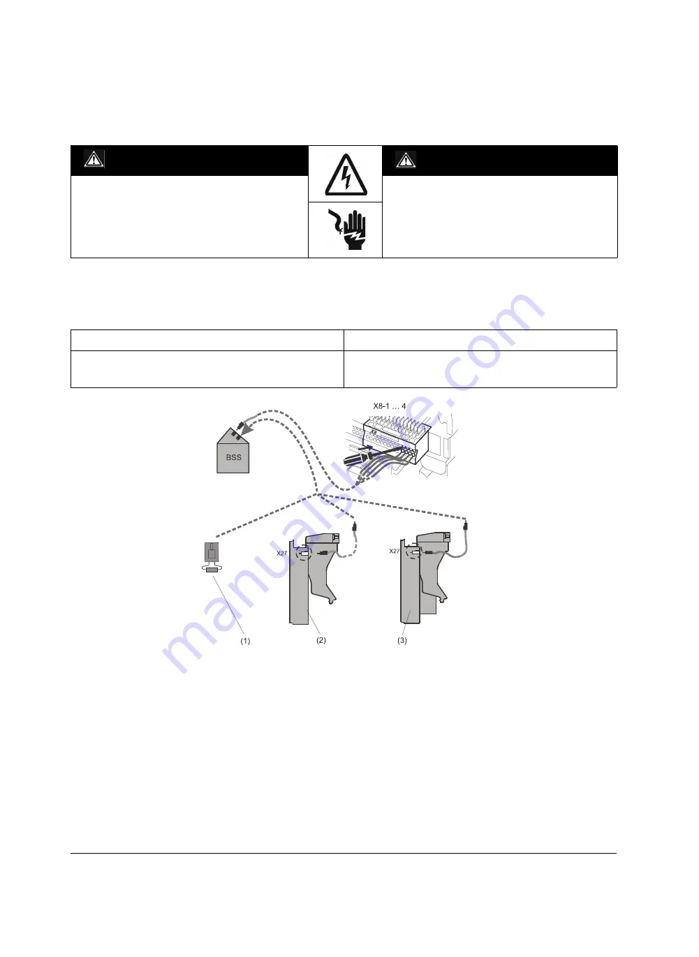
BSS-Modul anschließen
Der erste
-Anschluss führt an die Messerleiste X8. Der
zweite
-Anschluss erfolgt je nach Ausstattung des Lei-
stungsschalters.
q
Schaltpläne (Seite 8-1)
(1)
Abschlusswiderstand für ETU15B … 27B oder bei Leistungs-
trennschaltern
(2)
ETU45B … 76B ohne Messfunktion
(3)
ETU45B … 76B mit Messfunktion
GEFAHR
DANGER
Gefährliche elektrische Spannung!
Kann Tod, schwere Personenschäden sowie Schäden an
Geräten und Ausrüstung bewirken.
Vor dem Arbeiten an diesem Gerät, Anlage unbedingt span-
nungs freischalten.
Hazardous voltage!
Will cause death, serious personal injury, or equipment /
property damage.
Disconnect power before working on this equipment.
Hinweis
Note
Ggf. fehlende Hilfsstromanschlüsse nachrüsten (Messerleiste,
Hilfsstromstecker, Schleifkontaktmodul für Einschubrahmen).
q
(Seite 5-19)
If necessary missing auxiliary terminals may be retrofitted
(receptacle, auxiliary connectors and sliding contact module
for guide frames).
q
(page 5-19)
Connecting BSS-module
The first
connection leads to the male connector X8.
The second
connection is performed according to the
circuit-breaker equipment.
q
Circuit diagrams (page 8-1)
(1)
Terminating resistor for ETU15B ... 27B or at non-automatic
circuit-breakers
(2)
ETU45B ... 76B without metering function
(3)
ETU45B ... 76B with metering function
Summary of Contents for 3ZX1812-0WL00-0AN2
Page 91: ...9 15 S Auslösung I Auslösung S tripping I tripping ...
Page 92: ...9 16 Erdschlussauslösung Ground fault tripping ...
Page 121: ...English part continued on Page 9 60 9 45 ...
Page 135: ...English part continued on Page 9 60 9 59 ...
Page 149: ...9 73 ...
Page 307: ...19 10 Einbau Baugröße Frame size Länge L mm Length L mm I 48 II 118 III 232 1 Fitting ...
Page 317: ...20 2 Vertikal Vertical Einschubtechnik Draw out version Horizontal Horizontal ...
Page 362: ...5HOHDVH ...
Page 363: ...5HOHDVH 5 H OH D V H ...


