13 – 2
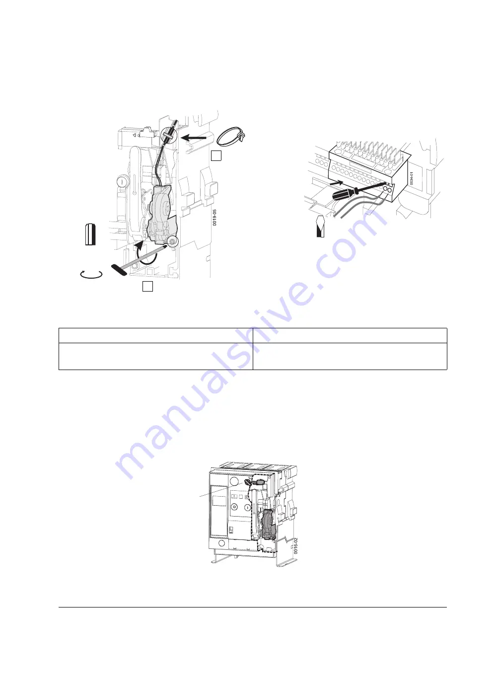
Motorantrieb befestigen / Leitungen anschließen
q
Schaltpläne (Seite 8-5)
13.2
Motorabstellschalter am Bedienpult
Option.
Zum Abschalten der Steuerspannung des Motorantriebs.
Lieferung vorkonfektioniert mit einer angelöteten Leitung.
Hinweis
Note
Ggf. fehlende Hilfsstromanschlüsse nachrüsten (Messerleiste,
Hilfsstromstecker, Schleifkontaktmodul für Einschubrahmen).
q
(Seite 5-19)
If necessary missing auxiliary terminals may be retrofitted
(receptacle, auxiliary connectors and sliding contact module
for guide frames).
q
(page 5-19)
1
2
6 Nm
Gr. / Size
5
Nicht möglich bei vorhandenem „Elektrisch Ein“
Not possible if "electrical ON" available
Fixing the motor operating mechanism /
connecting wires
q
Circuit diagrams (page 8-5)
13.2
Motor disconnect switch at the front panel
Option.
For de-energizing the motor operating mechanism.
Supplied pre-assembled with one soldered wire.
3,0 x 0,6
X5
Klemmen / Terminals:
X5.1 (L-)
X5.2 (L+)
Summary of Contents for 3ZX1812-0WL00-0AN2
Page 91: ...9 15 S Auslösung I Auslösung S tripping I tripping ...
Page 92: ...9 16 Erdschlussauslösung Ground fault tripping ...
Page 121: ...English part continued on Page 9 60 9 45 ...
Page 135: ...English part continued on Page 9 60 9 59 ...
Page 149: ...9 73 ...
Page 307: ...19 10 Einbau Baugröße Frame size Länge L mm Length L mm I 48 II 118 III 232 1 Fitting ...
Page 317: ...20 2 Vertikal Vertical Einschubtechnik Draw out version Horizontal Horizontal ...
Page 362: ...5HOHDVH ...
Page 363: ...5HOHDVH 5 H OH D V H ...


