9 – 25
If the zone selective interlocking (ZSI)
q
is used and
the ZSI module is set to "S" or "S+G" the adjusted delay time t
g
is
automatically set to 100 ms provided that in the event of earth-fault
the circuit-breaker does not receive a blocking signal from a down-
stream circuit-breaker. In this case regardless of the adjusted t
g
value the circuit-breaker will trip after 100 ms. If a blocking signal
exists the adjusted delay time t
g
is valid. For safety reasons after 3 s
the blocking signal is terminated.
Some overcurrent releases can be switched over to an I
2
t-charac-
teristic.
Neutral conductor protection – N-tripping
The overcurrent releases ETU27B ... 76B offer the possibility to pro-
tect the neutral conductor against overload, too. This requires a cur-
rent transformer for the neutral conductor, which can be retrofitted if
necessary.
q
As for tripping, the same time-lag class t
R
applies as for overload
tripping.
1)
Current settings above 1.0 x I
N
are only available for 3-pole circuit-breakers.
9.1.9.2 Additional functions
Load monitoring (load restore/load shedding)
The overcurrent releases ETU45B ... ETU76B offer the possibility of
additional load monitoring. Two current values, "load shedding" and
"load restore", as well as a delay time t
x
, can be set.
If the actual load falls below the setting "load restore" but simulta-
neously exceeds the "minimum of communicated currents" parame-
ter a signal is generated through the
after the set delay
time t
x
has elapsed. Also if the the actual load exceeds the setting
"load shed" a signal is generated through the
after the
delay time t
x
has elapsed. These signals can be used to connect or
disconnect loads, thereby preventing an overload tripping of incom-
ing circuit-breakers.
Load monitoring can be adjusted through:
- the alphanumeric display (ETU45B)
- the graphical display (ETU76B)
- the test socket with the BDA
- the PROFIBUS-DP with a PC and the software "Switch ES
Power".
- the Modbus with a PC and software
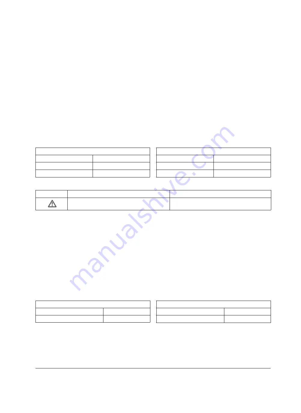
Setting values for I
N
ETU27B
I
N
= I
n
; OFF
ETU45B
I
N
= (0.5 / 1.0) × I
n
; OFF
ETU55B … 76B
I
N
= (0.2 … 2.0
1)
) × I
n
; OFF
Setting values for load monitoring
"Load shedding" and "load restore"
40 A … 1.5 x I
R
Delay time
t
x
= 1 … 15 s
Selektivitätssteuerung (ZSI) und am ZSI-Modul gewählter Schal-
terstellung „G“ oder „S+G“
q
für die Verzögerungszeit t
g
auf 100 ms gesetzt, wenn der Leistungs-
schalter im Erdschlussfall kein Blockiersignal von einem nachgeord-
neten Leistungsschalter erhält. Er schaltet dann unabhängig vom
eingestellten Wert für t
g
bereits nach 100 ms ab. Mit Blockiersignal
gilt weiter die eingestellte Zeit t
g
. Zur Sicherheit wird nach längstens
3 s das Blockiersignal beendet.
Für einige Überstromauslöser besteht die Möglichkeit, auf eine
I
2
t-Charakteristik umzuschalten.
Neutralleiterschutz – N-Auslösung
Die Überstromauslöser ETU27B … 76B bieten die Möglichkeit,
auch den Neutralleiter vor Überlast zu schützen. Dazu ist ein Strom-
wandler für den Neutralleiter erforderlich, der ggf. nachgerüstet wer-
den kann.
q
Für die Auslösung gilt der gleiche Trägheitsgrad t
R
, wie für die Über-
lastauslösung.
1)
Einstellwerte über 1,0 x I
n
stehen nur für 3polige Schalter zur Verfügung.
9.1.9.2 Zusätzliche Funktionen
Lastüberwachung („Lastaufnahme/Lastabwurf“)
Die Überstromauslöser ETU45B ... ETU76 B bieten die Möglichkeit,
den Laststrom zusätzlich zu überwachen. Es lassen sich zwei
Stromwerte, „Lastabwurf“ und „Lastaufnahme“, und eine Verzöge-
rungszeit t
x
einstellen.
Bei Unterschreiten des Einstellwertes „Lastaufnahme“ und gleich-
zeitigem Überschreiten des unteren Grenzwertes der Stromübertra-
gung wird nach Ablauf der eingestellten Verzögerungszeit t
x
über
den
eine Meldung ausgegeben. Bei Überschreiten des
Einstellwertes „Lastabwurf“ wird nach Ablauf der eingestellten Ver-
zögerungszeit t
x
über den
eine Meldung ausgegeben.
Diese Meldungen können zum Zu- bzw. Abschalten von Verbrau-
chern genutzt werden. Damit lassen sich z. B. Überlastauslösungen
von Einspeiseschaltern vorbeugend vermeiden.
Die Einstellung der Lastüberwachung kann erfolgen über:
- das alphanumerisches Display (ETU45B)
- das Grafikdisplay (ETU76B)
- die Prüfbuchse mit dem BDA
- den PROFIBUS-DP mit einem PC und der Software „Switch ES
Power“.
- den Modbus mit einem PC und dafür vorgesehener
Software
Einstellwerte für I
N
ETU27B
I
N
= I
n
; OFF
ETU45B
I
N
= (0,5 / 1,0) × I
n
; OFF
ETU55B … 76B
I
N
= (0,2 … 2,0
1)
) × I
n
; OFF
VORSICHT
CAUTION
Einstellwerte I
N
> 1 x I
n
nur bei entsprechender
Dimensionierung des N-Leiters verwenden!
Setting values I
N
> 1 x I
n
should only be used if the
neutral conductor has been sufficiently dimensioned.
Einstellwerte für Lastüberwachung
„Lastabwurf“ und „Lastaufnahme“
40 A … 1,5 x I
R
Verzögerungszeit
t
x
= 1 … 15 s
Summary of Contents for 3ZX1812-0WL00-0AN2
Page 91: ...9 15 S Auslösung I Auslösung S tripping I tripping ...
Page 92: ...9 16 Erdschlussauslösung Ground fault tripping ...
Page 121: ...English part continued on Page 9 60 9 45 ...
Page 135: ...English part continued on Page 9 60 9 59 ...
Page 149: ...9 73 ...
Page 307: ...19 10 Einbau Baugröße Frame size Länge L mm Length L mm I 48 II 118 III 232 1 Fitting ...
Page 317: ...20 2 Vertikal Vertical Einschubtechnik Draw out version Horizontal Horizontal ...
Page 362: ...5HOHDVH ...
Page 363: ...5HOHDVH 5 H OH D V H ...


