Siemens IK PI · 2004
6/109
AS-Interface Slaves
AS-Interface motor starters and IP65/67 load feeders
AS-Interface compact starters IP65 (400 V AC)
6
■
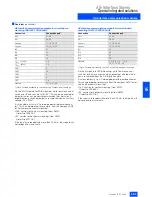
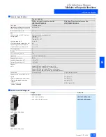
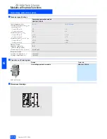
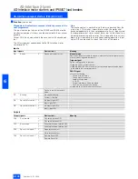
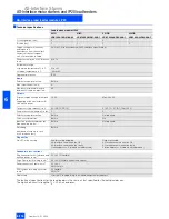
Technical specifications
DS/RS
EDS/ERS
Degree of protection
IP65 (with covered connecting elements and cover flap)
Material
Thermoplastic (glass-fibre reinforced)
Color
Anthracite RAL 7016
Cover flap
Latching, sealable
Dimensions (W x H x D) in mm
120
´
265
´
134
Temperature range
• Operating temperature in °C
-25 to +55 (derating must be observed: See manual)
• Storage temperature in °C
-40 to +70
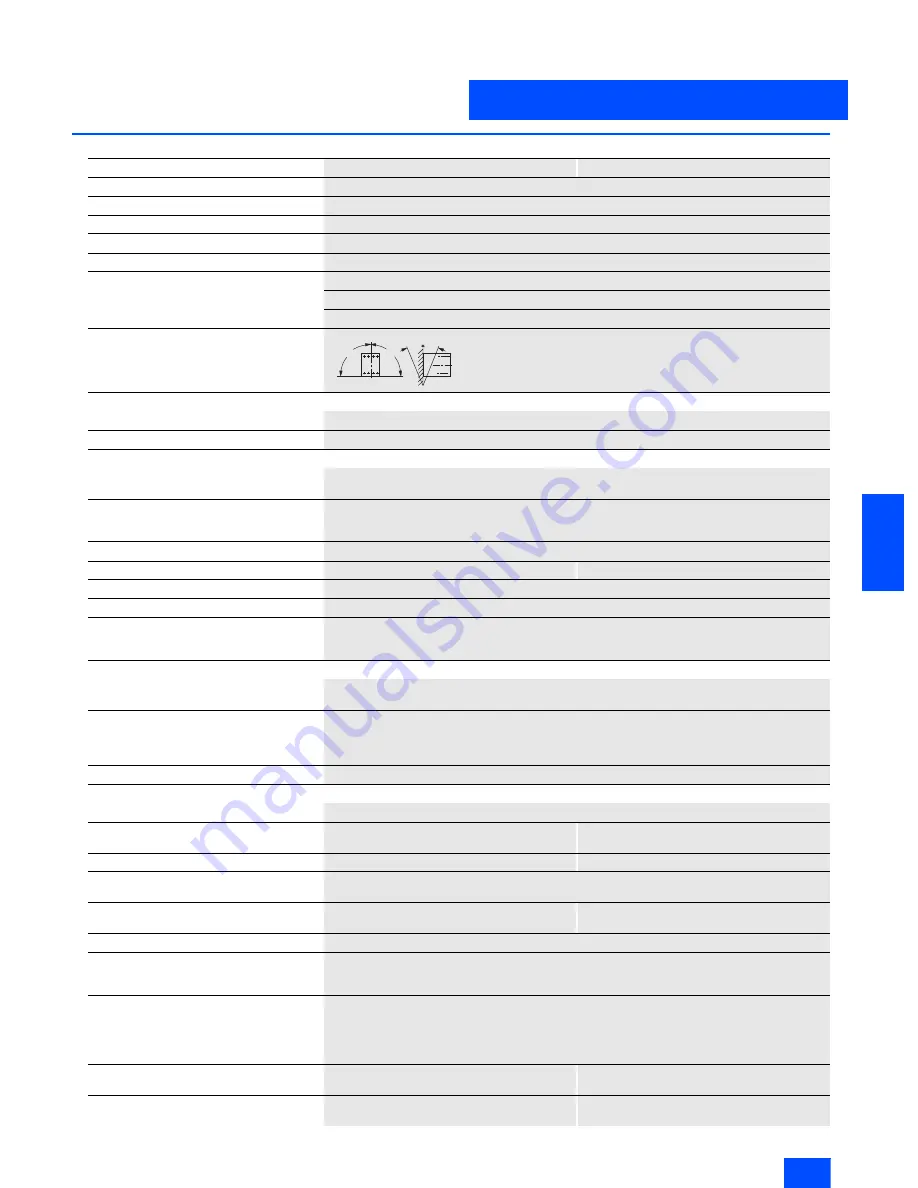
Permissible service position
Shock resistance
Rectangular pulse (g/ms)
2/unlimited, 10/5 or 5/10
Sine pulse (g/ms)
2/unlimited, 8/10 or 15/5
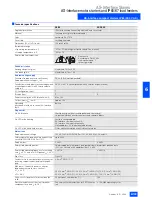
External voltage supply
For output supply (contactor activation)
Rated operational voltage
U
e
in V
DC 24 (PELV; must be earthed)
For electronics and inputs (acknowledgements
of switchgear status) via AS-Interface data
cable in V
DC 26.5 to 31.6 (in compliance with AS-Interface specification)
I/O configuration (hex)
7
ID code (hex)
D
E
Power consumption of AS-Interface in mA
Max. 100
Current input
U
Aux
in mA
Approx. 100
Watchdog
(shutdown of outputs in case of AS-Interface
fault)
Built-in
Diagnostics
Via AS-Interface
Checkback signal from circuit-breaker and contactor(s)
via positively-driven auxiliary contacts and separate inputs
Via LED at the housing
Auxiliary voltage applied
AS-Interface communication OK
AS-Interface communication faulty
Station address = 0 (module not addressed)
Via LED at the hand-held terminal
ON or clockwise rotation or anti-clockwise rotation
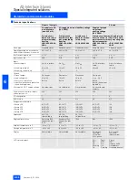
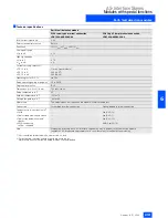
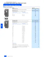
Main circuit
Rated operational voltage
500 V AC to DIN VDE 0106 Part 101, AC 600 V to CSA and UL
Safety separation between main and auxiliary
circuit (to DIN VDE 0106, Part 101)
up to 400 V
-
Rated output
5.5 kW
2.2 kW
Permissible operating duties
Uninterrupted duty, temporary duty, periodic duty, intermittent periodic duty
(50 % rel. ON-time at 80 operations/h at 5.5 kW)
Permissible operating frequency for a starting
time
t
A
= 0.1 s and a rel. ON period
t
EP
= 50 %
£
80 1/h
£
600 1/h
Trip class
Class 10
Conductor cross-section for power connector
incoming supply/ feeder/ looping through 9-
pole
£
4 mm
2
, AWG 15-11
Max. perm. current via power connector
(dependent on cable cross-section)
•
T
u
= 60 °C
30 A (4 mm
2)
, AWG (11); 20 A (2.5 mm
2)
), AWG (15); 12 A (1.5 mm
2
), AWG (13)
•
T
u
= 40 °C
35 A (4 mm
2)
, AWG (11); 25 A (2.5 mm
2
), AWG (15); 15 A (1.5 mm
2
), AWG (13)
Short-circuit strength of starter combination
in kA
50 (to type of co-ordination "1")
100
Electrical endurance of the circuit-breaker
component for a load I
a
(AC-3)
See service-life characteristics for 3RT10 contac-
tors
³
10 million operating cycles
N
S
A
0_
00
10
4
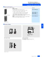
2 2 , 5 ° 2 2 , 5 °
9 0 °
9 0 °
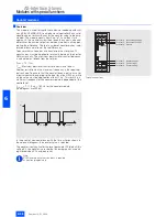
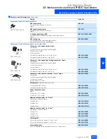
Please note:
According to DIN 43 602
start-up command ”I“
to the right or top

