Siemens IK PI · 2004
6/114
AS-Interface Slaves
AS-Interface motor starters IP67 (24 V DC)
AS-Interface motor starters and IP65/67 load feeders
6
■
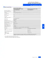
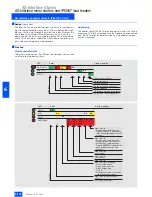
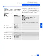
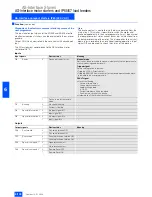
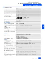
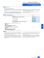
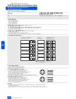
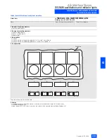
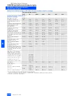
Technical specifications
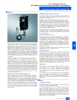
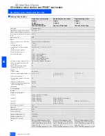
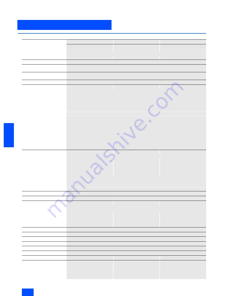
Single direct on-line starter
Double direct on-line starter
Single reversing starter
4 inputs
4 inputs
4 inputs
1 output
2 outputs
1 output
Quickstop function
3RK1 400-1NQ01-0AA4
3RK1 400-1MQ01-0AA4
3RK1 400-1MQ03-0AA4
Slave type
Standard slaves
Operational voltage in accordance
with AS-Interface specification in V
26.5 to 31.5
Total current input from AS-Interface
in mA
£
270
Input connection
PNP
Inputs
• Sensor supply via AS-Interface
Short-circuit and overload proof
• Sensors
3-wire
• Voltage range in V
20 to 30
• Load rating for sensor supply
in mA
200 (
T
u
£
40 °C) / 150 (
T
u
£
55 °C)
• Switching level High in V
³
10
• Switching level Low in V
£
5
• Socket assignment
PIN 1 = Sensor supply L+
PIN 2 = Data input
PIN 3 = Sensor supply L-
PIN 4 = Data input/Quickstop
PIN 5 = Earth connection
• External voltage supply DC 24 V
Via black AS-Interface flat cable
• Max. start-up ramp time for DC
motor in ms
80
• Max. motor start-up current
(internally limited) in A
4.5
Outputs
• Type of output
Electronics
• Nominal load rating per output in A 3 (
T
u
£
55 °C)
-
1 x 3 (
T
u
£
55 °C)
2 x 2 (
T
u
£
55 °C)
2.5 (
T
u
£
55 °C)
-
• Max. total current in A
-
4
-
• Voltage drop (without incoming
line) in V
0.6
1.2
• Short-circuit protection
Built-in
• Inductive interference protection
(free-wheeling diode)
Built-in
• Watchdog
Built-in
I/O configuration
7
ID code
F
Assignment of data bits
• Socket 1
PIN4 = IN1 (D0 / Quickstop1)
PIN2 = IN2 (D1)
• Socket 2
PIN4 = IN3 (D2)
PIN2 = IN4 (D3)
PIN4 = IN3 (D2 / Quickstop2)
PIN2 = IN4 (D3)
• Socket 3
PIN4 = OUT1(D0)
PIN4 = OUT1(D0)
PIN2,4 = OUT1 (D0, D1)
• Socket 4
-
PIN4 = OUT2(D1)
-
AS-Interface certificate
Yes
Approvals
UL, CSA
Degree of protection
IP67
Earth connection
Yes
Ambient temperature in °C
-25 to +55
Storage temperature in °C
-40 to +85
Number of I/O sockets
3
3
Note
Max. switching frequency when
activating, e. g. a 10 W DC motor
(
U
Aux
= 28.8 V/duty cycle = 50 %):
•
T
u
max
/°C: 55
• Max. switching frequency/h: 1500
Max. switching frequency when
activating, e. g. a 10 W DC motor
(
U
Aux
= 28.8 V/duty cycle = 50 %):
•
T
u
max
/°C: 55
• Max. switching frequency/h: 1500
Max. switching frequency when
activating, e. g. a 10 W DC motor
(
U
Aux
= 28.8 V/duty cycle = 50 %):
•
T
u
max
/°C: 55
• Max. switching frequency/h: 1000

