background image


Installation Instructions 

Document No. 570-136 

October 26, 2016 


Smoke Control Listed BACnet Fume 
Hood Controller 


Item No. 570-136. Rev. CA


Page 1 of 11 


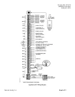
Generic Controller I/O Layout. See Wiring Diagram for application specific details. 


Control Applications 

6740, 6741 and 6742 

Product Description 

These instructions explain how to field install or 

replace the Fume Hood Controller (FHC). 
This BACnet Fume Hood Controls a Fast-acting 

Damper or Venturi Air Valve to maintain control of a 

chemical fume hood with up to 2 sashes. It uses 

fast-acting electronic actuators (shipped separately) 

to control the exhaust control device.  


WARNING 

The application cannot detect a 

broken wire to the analog input 

for the second sash. 
An external sash aggregating 

device should be used to 

calculate the face area for all 

fume hoods with more than one 

sash.  

This controller supports up to two Offboard AVS 

signals. Offboard Air Module(s) (OAM) house AVS 

transducers and send signals to the AVS input(s) on 

the controller board. The controller can operate 

stand-alone, with a field panel, or as part of a 

network. 
 

Summary of Contents for 570-00701PKA

Page 1: ...nturi Air Valve to maintain control of a chemical fume hood with up to 2 sashes It uses fast acting electronic actuators shipped separately to control the exhaust control device WARNING The application cannot detect a broken wire to the analog input for the second sash An external sash aggregating device should be used to calculate the face area for all fume hoods with more than one sash This cont...

Page 2: ...ne décharge électrostatique peut endommager la carte équipée Accessories Room Sensor Cable 25 ft Room Sensor Cable 50 ft 588 100A 588 100B Vertical Sash Sensor 50 inch range 80 inch range 546 04000 546 04001 Parts for Smoke Control Compliance Smoke Control Listed Large Equipment Controller Enclosure Long board and ATEC controllers 550 002K UL Listed Class 2 transformer with 120 240 277 480 Vac 50 ...

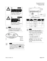
Page 3: ...esired location 2 Place the ESD wrist strap on your wrist and attach it to a good earth ground 3 Remove the controller from the static proof bag and snap it into place on the mounting rail 4 If the controller will be used with a field panel disconnect the field level network FLN trunk from the field panel 5 Wire the FLN trunk to the controller After all controllers are connected to the FLN reconne...

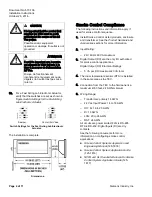
Page 4: ... and information apply if used for smoke control sequence 1 Install Smoke Control Listed products enclosure and transformer See the Product Numbers and Accessories sections for more information 2 Input Rating 24V 60 Hz 60 VA maximum 3 Digital Output DO are the only I O authorized for smoke control applications Digital Output DO Electrical Ratings 5 VA per DO maximum 40 VA total 4 The room temperat...

Page 5: ...ful interference to radio communications However there is no guarantee that interference will not occur in a particular installation If this equipment does cause harmful interference to radio or television reception which can be determined by turning the equipment off and on the user is encouraged to try to correct the interference by one of the following measures Reorient or relocate the receivin...

Page 6: ...re to the analog input for the second sash An external sash aggregating device should be used to calculate the face area for all fume hoods with more than one sash AVERTISSMENT L application ne peut pas détecter un fil rompu allant à une entrée analogique pour le second châssis Un dispositif externe de cumulation de châssis devrait être utilisé pour calculer la surface à l entrée de toutes les hot...

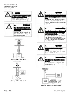
Page 7: ...en wiring any actuator that uses a 0 to 10V control signal and ties AC neutral to DC common an additional wire must connect the actuator AC neutral to the DC common of the PTEC TEC AO being used to control the actuator 24 Vac Modulating Control Actuator Symbol TEC Connection Function Terminal Connection Standard Color 1 H Supply SP G Red 2 C Neutral SN G0 Black 8 AO3 15 0 to 10V input signal Y Gra...

Page 8: ...Document No 570 136 Installation Instructions October 26 2016 Page 8 of 11 Siemens Industry Inc Application 6740 Wiring Diagram ...

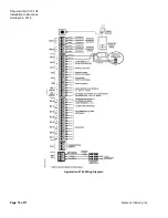
Page 9: ...Document No 570 136 Installation Instructions October 26 2016 Siemens Industry Inc Page 9 of 11 Application 6741 Wiring Diagram ...

Page 10: ...Document No 570 136 Installation Instructions October 26 2016 Page 10 of 11 Siemens Industry Inc Application 6742 Wiring Diagram ...

Page 11: ...curity management and physical security systems The security functions on these products solutions and services are important components of a comprehensive security concept Drafting implementing and managing a comprehensive and up to date security concept customized to individual needs is nevertheless necessary and may result in additional plant or site specific preventive measures to ensure secur...

Reviews: