instabus EIB
Technical Product Information
April 2003
DELTA Bus Coupling Unit UP 116
5WG1 116-2AB...
without physical external interface
Technical Manual
UP 116, 4 pages
Siemens AG
Automation and Drives Group
Update: http://www.siemens.de/gamma
ã
Siemens AG 2003
Electrical Installation Technology
Subject to change without prior notice
P.O.Box 10 09 53, D-93009 Regensburg
2.16.1.3/2
Technical Specifications
Power supply
via bus cable
Operator elements
1 learning button (combined with LED):
for switching between normal operating mode and
addressing mode
Display elements
·
1 red LED (combined with learning button):
for monitoring bus voltage and displaying mode,
selected with the learning button
·
2 red LEDs:
for use as orientation lights or for displaying the
current state (can be set in the parameter list)
Connections
·
bus line, screwless bus connection block:
Æ
0,6 ... 0,8 mm single core
remove approx. 5mm of isolation
·
single or twin rocker switch levers (as appropriate for
configuration) for sliding on DELTA rocker switches
Physical specifications
·
housing: plastic
·
dimensions:
-
W x H: 71 x 71 mm
-
mounting depth: 32 mm
·
weight: approx. 80 g
·
fire load: approx. 406 kJ
±
10 %
·
installation:
-
when connecting to a single bus cable only:
box mount: Ø 60 mm, 40 mm deep
-
when connecting to more than one bus cable
(looped through):
junction box mount: Ø 60 mm, 60 mm deep
Electrical safety
·
degree of pollution (according to IEC 60664-1): 2
·
protection (according to EN 60529): IP 20
·
protection class (according to IEC 61140): III
·
overvoltage class (according to IEC 60664-1): III
·
bus: safety extra low voltage SELV DC 24 V
·
device complies with
EN 50090-2-2 and IEC 60664-1: 1992
Reliability
rate of failure: 235 fit at 40
°
C
Electromagnetic compatibility
complies with
EN 50081-1, EN 50082-2 and EN 50090-2-2
Environmental specifications
·
climatic conditions: EN 50090-2-2
·
ambient temperature operating: - 5 ... + 45
°
C
·
storage temperature: - 25 ... + 70
°
C
·
relative humidity (non-condensing): 5 % to 93 %
Certification
EIB certificate
CE norm
complies with the EMC regulations (residential and
functional buildings), and low voltage regulations
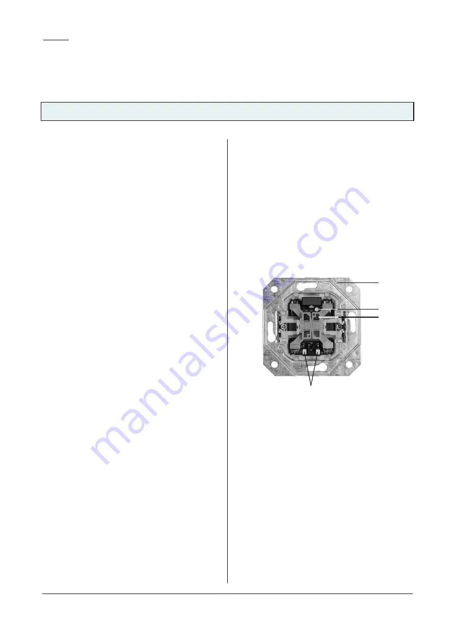
Location and Function of the Display and
Operator Elements
A4
A2
A3
A1
Figure 1: Location of the display and operator elements
A1 Mounting
hanger
A2 Learning button for switching between normal
operating mode and addressing mode combined
with the
LED for indicating normal operating mode (LED
off) and addressing mode (LED on); upon receiv-
ing the physical address the device automatically
returns to normal operating mode
A3 Single or double switching lever (depending on
configuration) for plugging on a DELTA rocker
A4 LEDs for displaying states or for use as orientation
lights


