background image

GAMMA 

instabus


Technical product information 

June 2010 

Switching actuator, main module N 513/11 

5WG1 513-1AB11 

3x AC 230/400V, 20AX, C-load, load-check  

Technical manual 

N 513/11, 6 pages 

Siemens AG  


Industry Sector, Building Technologies 

Update: http://www.siemens.com/gamma 

© Siemens AG 2010 

Low Voltage Distribution 


Subject to change without further notice 

P.O. Box 10 09 53, D-93009 Regensburg 

2.4.3.6/4 

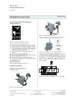
Location and function of the display and  

operating elements


A1

A4

A10

A11

A9
A8

A12

A6

A7

A5

A3

A2


Figure 2. Display and operating elements 
 

A1 

Plug for bus connection terminal block 

A2 

Button for switching between normal mode and ad-

dressing mode for transferring the physical address. 

A3 

LED for indicating normal mode (LED Off) or address-

ing mode (LED On); it turns off automatically after 

transferring the physical address 

A4 

Jack for connection of a switching actuator sub-

module 

A5 

LED to indicate the selected device 

A6 

Pushbutton to toggle between Bus and Direct mode 

A7 

LED to indicate Direct mode = On  

A8 

Pushbutton for direct operation of outputs 1...3 

A9 

LED to indicate whether the corresponding output is 

switched on or off. 

A10 

Without function 

A11 

Without function 

A12 

Screw-type terminals of outputs 1...3 


Installation and wiring 


Mounting / dismounting the device:  

see figure 3 and 4 


Figure 3. Mounting the device  


Figure 4. Dismounting the device  


Connecting / disconnecting the bus cable: see figure 5 
 

D2

D2.4

D2

D2.4

5 mm

D2.1 D2.2

2

D2.3

D


Figure 5. Connecting / disconnecting the bus cable 


Connecting a switching actuator submodule: see figure 6 

Snap the switching actuator sub-module on to the rail 
and push it to the left against the switching actuator 
main module or against the switching actuator sub-
module. Connect both devices using the bridging con-
nector supplied. 


A

B

C


Figure 6. Connecting a switching actuator sub-module 


B1 

B2 

C3 

C1 

C2 

Summary of Contents for 5WG1 513-1AB11

Page 1: ...o toggle between bus mode and direct mode If this pushbutton is pressed briefly the associated green LED indicates for 30 seconds which of the modules A to E see figure 2 A5 was se lected last and the switching state of the corresponding outputs is indicated by the red LED integrated in buttons 1 to 3 see figure 2 A9 relay contact closed LED ON contact open LED OFF However if the button to switch ...

Page 2: ...itoring of the load current for each output on load failure and or overload simultane ous switching of all 3 outputs 3 phase switching con version of a speed given as a percentage value into 1 to 3 stage switching commands fan speed control con version of a valve setting given as a percentage value into a pulse width modulated PWM switching com mand thermal drive control a switching cycle and oper...

Page 3: ...9 outputs 5 with 12 outputs 4 with 15 outputs Operating elements 1 commissioning push button for toggling between normal mode addressing mode 1 push button for toggling between bus mode direct mode 6 push buttons for direct operation toggling of up to 6 actuator out puts independent of the bus Display elements 1 red LED for checking the bus voltage and for display ing normal mode addressing mode 5...

Page 4: ... Jack for connection of a switching actuator sub module A5 LED to indicate the selected device A6 Pushbutton to toggle between Bus and Direct mode A7 LED to indicate Direct mode On A8 Pushbutton for direct operation of outputs 1 3 A9 LED to indicate whether the corresponding output is switched on or off A10 Without function A11 Without function A12 Screw type terminals of outputs 1 3 Installation ...

Page 5: ... further notice 2 4 3 6 5 Dimension drawing Dimensions in mm b 90 44 55 45 b 3 module units 1 module unit MU 18 mm General notes The operating instructions must be handed over to the client A faulty device shall be sent with a Return Good Note for Service provided by the appropriate Siemens sales office to the following address SIEMENS AG Siemensstr 10 D 93055 Regensburg If you have further questi...

Page 6: ... 1AB11 3x AC 230 400V 20AX C load load check Technical manual N 513 11 6 pages Siemens AG Industry Sector Building Technologies Update http www siemens com gamma Siemens AG 2010 Low Voltage Distribution Subject to change without further notice P O Box 10 09 53 D 93009 Regensburg 2 4 3 6 6 Space for notes ...

Reviews: