Infrastructure and Mobility, Traffic Solutions
Sopers Lane, Poole, Dorset
BH17 7ER
Version
7
Page 39 of 76
Status
ISSUED
Last Editor
Ore Oluwatudimu
TS008468
Date
31/01/2017
Document
Name
UPS Solution General Handbook
Doc. No.
667/HB/47750/000
Copyright
Siemens plc 2017 All Rights Reserved
5.
Connect the positive ring tag from the housing MCB to the positive terminal of
Battery 4. (brown cable)
6.
Replace the battery retention bar.
9.12 Fitting the Battery Temperature Sensor
Step No.
UPS Cabinet
Battery Expansion Cabinet
Refer to
11
Connect the Batt. Temp.
sensor
N/A
Section 9.12
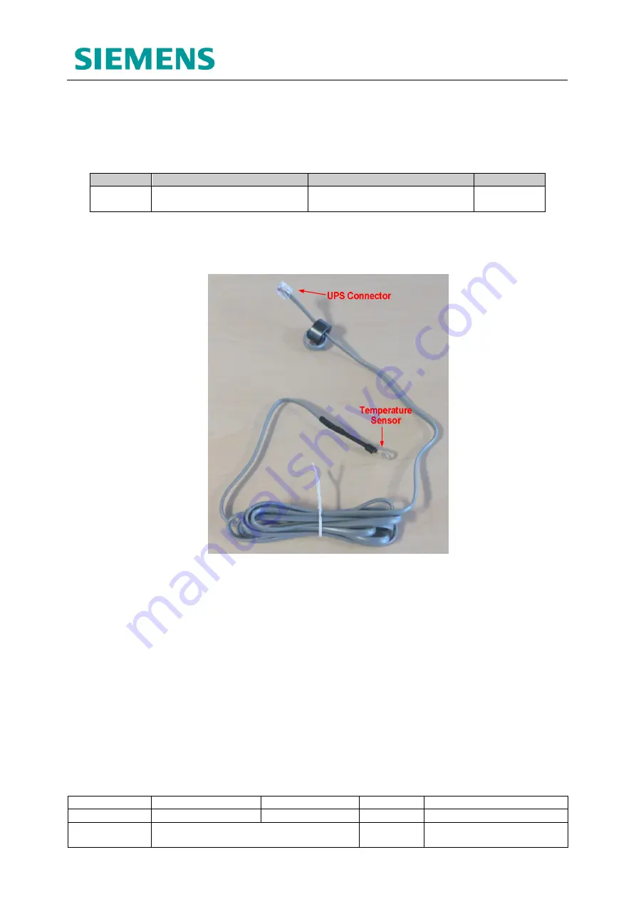
This sensor allows the FXM UPS unit to temperature compensate its battery charging
characteristics and is a vital part of the system installation. The sensor is to be fitted as
follows to the battery pack housed directly below the UPS unit.
Figure 9-11: Battery Temperature Sensor
1.
Ensure the temperature sensor connector is securely fitted into the ‘BATTERY
TEMP’ socket of the FXM UPS unit.
2.
Use tape to fix the sensor ring terminal to the exposed side of Battery 2.
3.
On mounting Battery 3, ensure that it is flush with Battery 2 creating a secure fit
for the battery temperature sensor.
4.
Tidy away the Battery Temperature Sensor cable.


