Infrastructure and Mobility, Traffic Solutions
Sopers Lane, Poole, Dorset
BH17 7ER
Version
7
Page 47 of 76
Status
ISSUED
Last Editor
Ore Oluwatudimu
TS008468
Date
31/01/2017
Document
Name
UPS Solution General Handbook
Doc. No.
667/HB/47750/000
Copyright
Siemens plc 2017 All Rights Reserved
12.2.2 Fault Monitoring using Siemens RMS and UTMC Systems
The UPS Solution’s fault / alarm relay contacts can be used to send indications back to
the central office Instation via an OTU or OMU
. The following are the recommended
naming conventions for bit and possible connection scenarios.
Bit
Description
ONBAT (C1)
On Battery support. UPS is in inverter mode. Site mains is off
Usually HLD WARN (C4) below is recommended for this
purpose.
LOWB1 (C2)
Low Battery Warning 1 – Urgent indication that the UPS is
approaching its maximum support time and action should now
be taken to either provide additional support or take other
action (suitable site signing etc).
HLD WARN (C4)
Hold Up Warning. Triggered from the Timer alarm (5
minutes), Urgent indication that the UPS is powering the load
(Avoids nuisance reports when short mains breaks occur).
UPS ALRM (C5)
UPS Alarm. Urgent – There is a fault with the UPS. Site visit
or remote investigation required.
Table 12-3: RMS Bit Labelling and Description
Example Scenario:
The LOWB1 (C2) contact can be used in two ways. The first is as an indication to the
controller that the UPS has been running on battery power for some time, allowing
special conditions or similar controller logic to perhaps dim lights or put the junction into a
flashing state to prolong support.
NOTE:
Customers should decide on a site by site basis if the use of dimmed
signals during the day is acceptable.
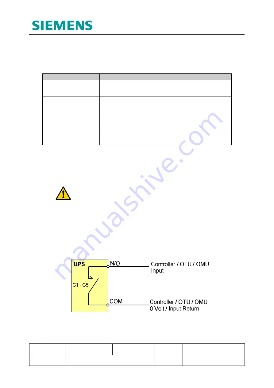
The second would be to pass this back through an OTU or OMU to a central office
Instation to warn that the UPS has used more than half of its back up supply.
All contacts
6
can either be passed through the controller (i.e. controller input to output to
OTU/OMU input to Instation) or may be connected directly to the OTU/OMU inputs for
forwarding to the central office Instation.
Review the controller and any OTU/OMU configurations supplied by the customer to
determine the connections that need to be made.
Figure 12-1: Fault Monitoring Connectivity Example
6
C6 is not to be used with Siemens traffic equipment. See section 12.2.1


