Infrastructure and Mobility, Traffic Solutions
Sopers Lane, Poole, Dorset
BH17 7ER
Version
7
Page 23 of 76
Status
ISSUED
Last Editor
Ore Oluwatudimu
TS008468
Date
31/01/2017
Document
Name
UPS Solution General Handbook
Doc. No.
667/HB/47750/000
Copyright
Siemens plc 2017 All Rights Reserved
6 Internal Cabling Scheme
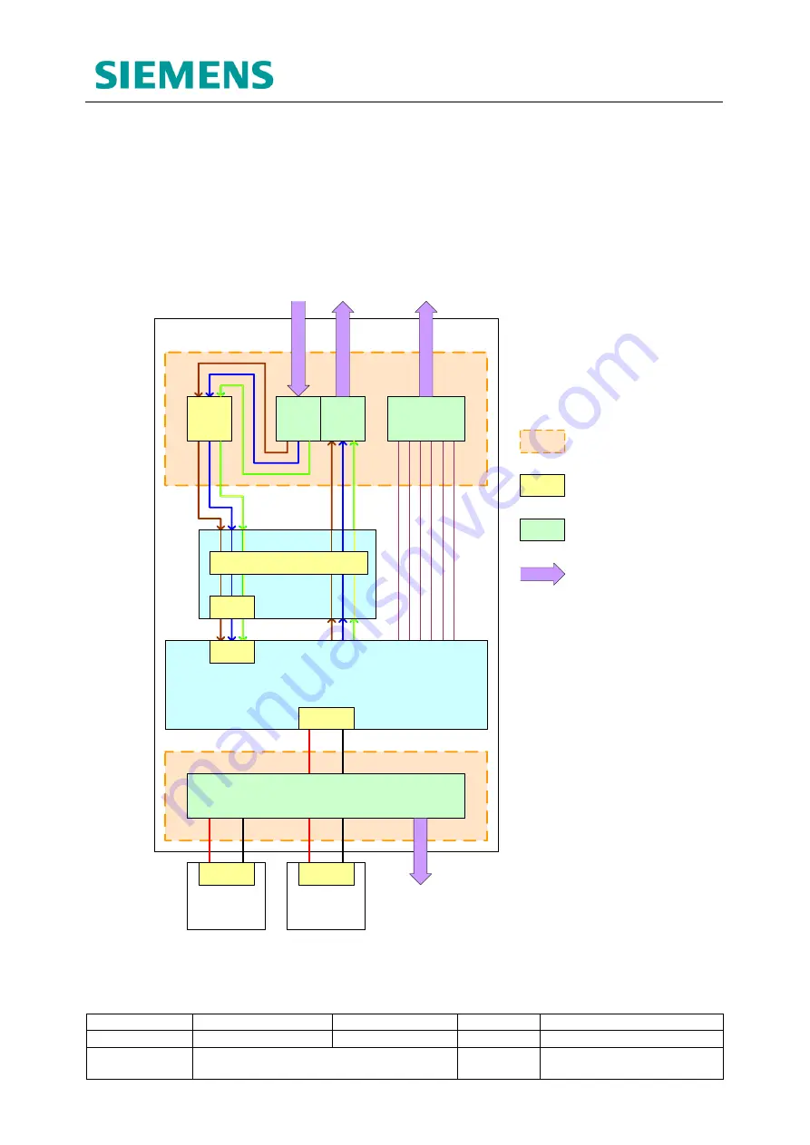
The UPS Housing, DC Housing and Battery Housing modules all come fitted with pre-
wired cable looms for ease of installation. The following subsections detail the internal
wiring interconnecting key system elements in both the UPS and Battery Expansion
cabinets.
6.1 UPS Cabinet Internal Wiring
BATTERY
HOUSING 1
BATTERY
HOUSING 2
MCB
C1 – C6
Faults/Alarms
54VDC BUS
B / -
Mains
IN
Mains
OUT
MCB
MCB
Alpha FXM Series UPS Unit
Mains
I/P CB
Battery CB
UATS
UPS
ON/OFF
UPS / BYPASS
Mains O/P
Fault Contacts
Mains
Supply
Controller
Supply
UPS Connection Panel
DIN Rail Terminal Block
Switch or Circuit Breaker
UPS HOUSING
Controller I/O
Card
Battery Expansion
Cabinet
External Cabling
Figure 6-1: UPS Cabinet Internal Wiring Diagram
As stated in section 3.3.4, the UPS Housing module comes fitted and prewired with key
system elements and all internal cabling. External cables are to be terminated within the
UPS Connection Panel as part of the Installation process. See section 9.8 for details.


