Infrastructure and Mobility, Traffic Solutions
Sopers Lane, Poole, Dorset
BH17 7ER
Version
7
Page 32 of 76
Status
ISSUED
Last Editor
Ore Oluwatudimu
TS008468
Date
31/01/2017
Document
Name
UPS Solution General Handbook
Doc. No.
667/HB/47750/000
Copyright
Siemens plc 2017 All Rights Reserved
9.5 Fitting and Connecting the Battery Housing Module
Step No.
UPS Cabinet
Battery Expansion Cabinet
Refer to
4
Fit and connect the Battery Housing module(s)
Section 9.5
The Battery Housing Module design allows them to be stacked unto each other. A
varying number of battery housing modules can be fitted depending on specific site
requirements.
WARNING:
Batteries
MUST NOT
be fitted within the Battery Housing module
during installation.
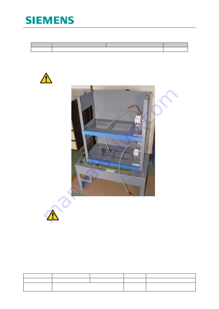
Figure 9-4: Battery Housing Modules stacked on the Reinforced Stool (Cabinet
removed)
NOTE:
Secure external cables from the CET plate to the cable
management holes in the left hand side of the Battery Housing modules as
each module is installed
Fitting the first Battery Housing Module:
1.
Pass the first battery housing through the front door aperture of the cabinet outer
case and place unto the raised box section ‘top hats’ of the reinforced stool.
2.
Align the countersunk holes in the bottom of the battery housing with the
threaded holes in the ‘top hats’, then secure into place using the Alan key and
fixings provided.
3.
Pass the loose earth wire from the right side of the battery housing through the
opening in the housing bottom and secure to the marked earth stud on the box
section ‘top hat’ below.


