Assembly and Installation Information
SIPART DR22/DR24
C79000-M7474-C38-01
18
5.4
Insertion of Modules
The modules are inserted from the rear side of the device and locked.
Important:
-
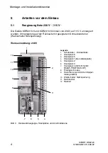
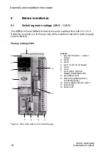
See Figure 2 for the slots.
-
The slots are coded.
-
The slot layout and the allocation of the inputs and outputs are assigned by
programming.
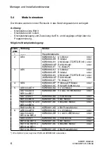
Possible slot layout:
Slot
Action
Module
1
--------
main circuit board
2
AE4
6DR2800-8J U/I module
or
6DR2800-8R R module
or
6DR2800-8V UNI module (TC/RTD/R/mV) or
(6DR2800-8P Pt100 module
or
6DR2800-8T TC module) *)
3
AE5
6DR2800-8J U/I module
or
6DR2800-8R R module
or
6DR2800-8V UNI module (TC/RTD/R/mV) or
(6DR2800-8P Pt100 module
or
6DR2800-8T TC module *)
4
SES
6DR2803-8P Profibus DP module
or
6DR2803-8C RS232/RS485 module
5
AE9 to AE11
6DR2800-8A 3 x U/I module
or
AA7 to AA9
BE5 to BE7
6DR2802-8B 3 x AA/ 3 x BE module
or
AA7 and St
6DR2802-8A y-hold module
or
BE5 to BE9
6DR2801-8C 5 BE module
or
BA9 to BA12 and
BE5 to BE6
6DR2801-8E 4 BA/2BE module
or
BA9 to BA10
6DR2801-8D 2 BA relay module
6
AE6 to AE8
6DR2800-8A 3 x U/I module
or
AA4 to A6
BE10 to BE12
6DR2802-8B 3 x AA/3 x BE module
or
AA4 and St
6DR2802-8A y-hold module
or
BE10 to BE14
6DR2801-8C 5 BE module
or
BA13 to BA16 and
BE10 to BE11
6DR2801-8E 4 BA/2BE module
or
BA13 to BA14
6DR2801-8D 2 BA relay module
*) We recommend the installation of the UNI module 6DR2800-8V.

