Functional description
Carrier controller
12
Operating Instructions, 09/2013, A5E03474162-02
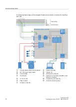
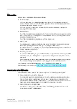
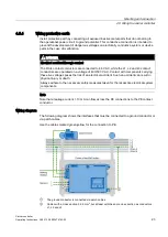
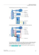
The following figure shows a block diagram of the carrier controller on which all connections
are in use.
①
Current collector carrier with 6 collectors
⑧
Sensors (optional)
②
24 V DC power supply module
⑨
Display unit
③
Circuit breaker
⑩
Brake resistor (optional)
④
On-off switch
⑪
Geared motor for travel of the EMS carrier
along the rail system
⑤
S7-1212C CPU
⑫
Programming unit (optional)
⑥
PSB-C module
⑬
IR remote control (optional)
⑦
Frequency converter

